255-700-166
7-117
PacketStar
®
PSAX 6-Port DS1 IMA Module User Guide
, Issue 1
Release 7.0
Chapter 7 Provisioning Connections Using the Console Interface
Provisioning SVC Connections
Adding VBR-to-ATM VCC SPVC Connections
Creating a VBR-to-
ATM Connection
Perform the steps in the following procedure to create an VBR-to-ATM SPVC
connection.
Begin
Steps to Create a VBR-to-ATM SPVC Connection
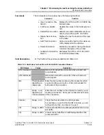
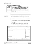
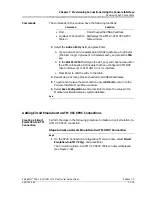
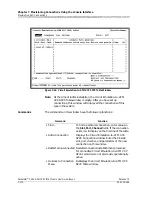
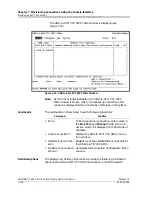
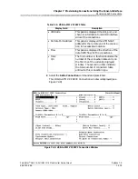
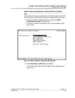
To add a VBR-to-ATM VCC SPVC connection, proceed as follows.
1
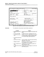
On the SPVC Connection Configuration Menu window, select
VBR-to-
ATM VCC(w)
, and press Enter.
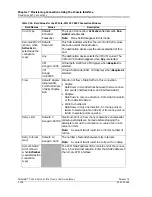
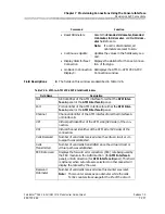
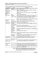
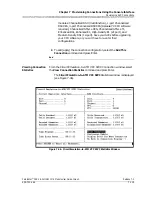
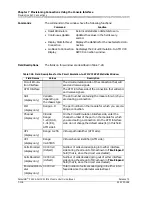
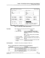
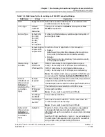
Decoded Odom-
eter
(display only)
0.0000 e0
(default)
Total number of cells decoded going out of either inter-
face side since the odometer was last reset.
Time Elapsed
(display only)
Time elapsed since the circuit was established.
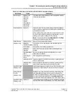
Time Since
Reset
(display only)
Time elapsed since the last time the
Reset Odometers
command was used. This command resets only the
odometer fields and the corresponding clock. Other
counters increment for the life of the circuit.
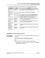
Cells Received
(display only)
6.5000 e1
(default)
Number of valid cells received since the virtual circuit
or virtual path was established.
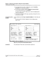
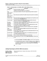
Cells
Transmitted
(display only)
6.5000 e1
(default)
Number of valid cells transmitted since the virtual cir-
cuit or virtual path was established.
Received
Odometer
(display only)
6.5000 e1
(default)
Total number of ATM cells received since odometer was
last reset.
Transmitted
Odometer
(display only)
6.5000 e1
(default)
Total number of ATM cells transmitted since odometer
was last reset.
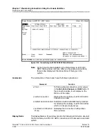
Table 7-28. Field Descriptions for the Circuit Emulation-to-ATM VCC SPVC Statistics Window
Field Names
Values
Description

