Installation
Connecting the Unit
to the PARTNER II Release 3 System
1.
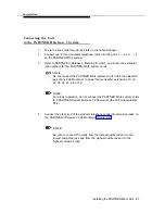
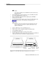
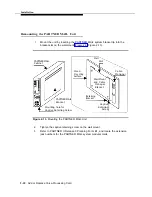
Route the line cords through the slots on the cable manager.
2.
Connect two (or four) modular telephone cords into the ports 1 — 2 or 1 — 4
on the PARTNER MAIL system.
3.
Refer to PARTNER II Release 3 Planning Form B1, and locate the extension
jack numbers for the PARTNER MAIL system cords.
NOTE:
Do not connect the PARTNER MAIL system cords to the top extension
jack of any 206 Module or to power failure transfer extensions 10, 16,
22, 28, 34, 40, 46, or 52.
NOTE:
For proper operation, do not connect the PARTNER MAIL system cords
to a PARTNER System Release 1 206 module (the 206 module Iabled
R1.0).
4.
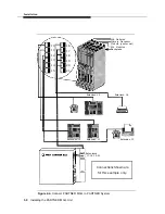
Connect the other end of the modular telephone cords into extension jacks on
the PARTNER II Release 3 206 Module(s) (Figure 2-4).
NOTE:
Be sure to connect the cords from the lowest-numbered port to the
lowest-numbered jack and from the highest-numbered port to the
highest-numbered jack.
Installing the PARTNER MAIL Unit
2-7

