363-205-401
Power Up: DLP-534
Issue 7, March 1997
Page 5 of 6
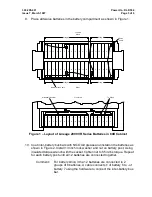
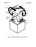
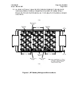
11. Cut a notch in the cover of the battery No. 1 (above "
−
" battery post) and bat-
tery No. 12 (above "+" battery post) (see Figure 2). This is required to install
the battery string cable.
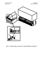
12. Connect the battery string cable to battery No. 1 by terminating the lug marked
BAT 1 (
−
) to the "
−
" (negative) battery post of the first battery in the string (Fig-
ure 2). Connect the battery string cable to battery No. 12 by terminating the lug
marked BAT 12 (+) to the "+" (positive) battery post of the 12th battery as
shown in Figure 2. Install the lock washer and nut on the battery posts. Use
insulated torque wrench to tighten the nuts to 55 in-lbs torque.
13. Coat each battery connection with NO-OXid grease.
14. Condition DMM to measure DC volts. Measure battery string voltage at the
connector (marked STR "+" and "
−
") at the end of the battery string cable.
Make sure measured polarity corresponds with polarity indicated on connec-
tor.
15. Does meter indicate battery string voltage between
−
50.4 V DC and
−
51.4 V
DC?
If YES, then proceed to Step 16.
If NO, then continue with Step 15.
16. Make sure that there are twelve batteries in the string. Recheck battery con-
nections and correct if necessary. If connections are correct, check individual
battery voltage. Any battery that indicates less than 4.20 V DC should be
replaced.
17.
!
DANGER:
After the connector from the control & distribution panel is mated with the
connector from the battery string cable, the power bus on the control &
distribution panel will be "live" (that is, have voltage on it).
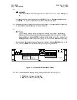
Connect the battery string cable STR connector to the connector designated
STR( ) (1, 2 or 3) on the end of the battery cable located in the battery com-
partment.
18. Dress cables in the battery compartment.


