Power Up: DLP-536
363-205-401
Page 2 of 4
Issue 7, March 1997
P114/J114 connection and verify that the power equipment DC circuit breaker
is not tripped. Refer to appropriate SD drawings to clear power trouble.
Replace the control circuit pack in the 4A or 4B fan unit if no power troubles
are found. Then repeat this procedure.
6.
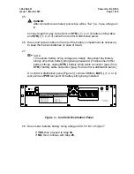
When the FAULT indicator is lighted, look through the front grille at the control
circuit pack.
• If the control circuit pack YELLOW indicator is lighted and the GREEN
LED is flashing, the thermal sensor may have failed. Check the voltage
between TEMP + and
−
jacks (1 volt DC per 10
°
C above 0
°
C). If the volt-
age indicates a temperature close to the ambient air, unplug and recon-
nect P114/J114 connector. If the voltage indicates a temperature
obviously too high or too low, replace the control circuit pack in the 4A or
4B fan unit.
The thermal sensor alarm (YELLOW LED) will light if a temperature
change of more than 2.7
°
C has not occurred in the past three days. To
clear this alarm reconnect the P114/J114 connector. To test the sensor
check the voltage between TEMP + and
−
jacks while blocking air flow
from the fan unit. The voltage will rise if the sensor is functional.
• If the GREEN indicator is flashing and the RED and YELLOW indicators
are off, one or both fans is obstructed or defective (for example, rotates at
less than 2000 RPM). Clear obstruction and/or replace defective fan.
• With the FAULT LED lighted and any other combination of control circuit
packs indicators, replace the control circuit pack in the 4A or 4B fan unit.
7.
Repeat this procedure after correcting trouble.

