DT Turn Up: DLP-500
363-205-401
Page 2 of 4
Issue 7, March 1997
2.
Remove cover to DC power interface by loosening the screw at the bottom of
the box, sliding the bottom out, and pushing down.
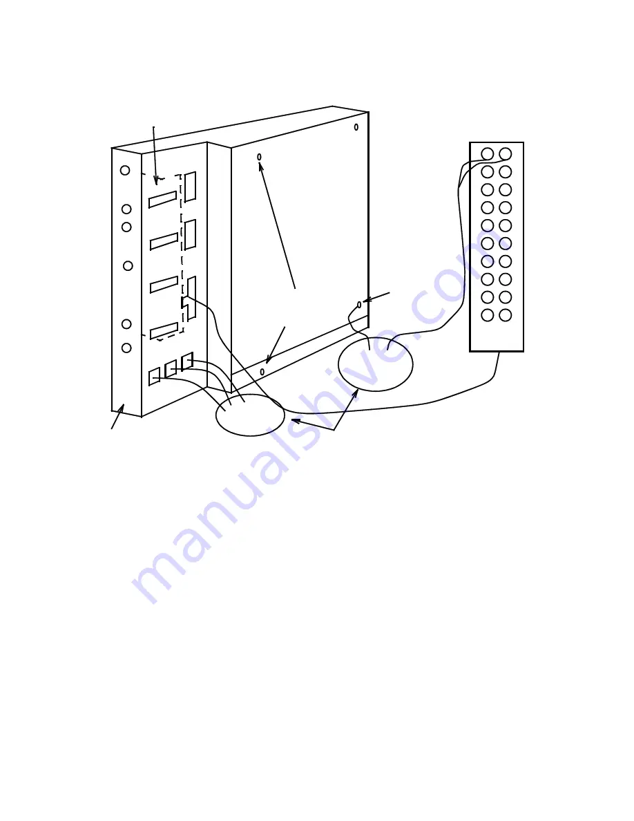
Figure 2 – DC Power Interface Connections
3.
Verify or make connections to the DC power module (Figure 2) as follows:
• Ground connection to the DC power interface circuit pack.
• 8-pair cable from DC drop terminal to J1.
• DC power cord for DT 1 to DT1.
• DC power cord for DT 2 to DT2.
• DC power cord for DT 3 to DT3.
• DC power cord for video equipment (if required) to VIDEO.
_
+
DC Power Feed
Terminal Block
Knurled
Retaining
Screws
DT Power
Cords
Cable
Pass-Through
DC
Power
Feed
Ground
Wire
Protector
Modules
Connect Ground
to this Screw
POWER
INTERFACE
1
VIDEO
24
GND
OUTPUT
ON
48RTN
-48
INPUT
ON
DT3
DT2
DT1
J1
AUX
4
3
2


