background image

1-2

Stinger® ADSL 48-Port Annex A LIM Guide

Configuring an ADSL 48-Port Annex A Line Interface Module (LIM)
Interpreting ADSL 48-port Annex A status lights

Interpreting ADSL 48-port Annex A status lights

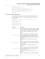
Several status lights on the front panel of the ADSL 48-port Annex A LIM indicate the status 
of the module and its ports. Figure 1-1 shows the front panel and status lights of the ADSL 
48-port Annex A LIM.

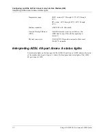
Temperature range 

FS/LT version: 32°F through 131°F (0°C through 
55°C)

RT version: -40°F through 149°F (-40°C through 
65°C)

Interface standards

ANSI T1E1.4/99-006 (draft).

Network Timing Reference 
(NTR)

An 8kHz reference clock is provided over the 
ADSL line for any CPE with the capability to 
recover it.

Physical connectors

USOC RJ21X 50-pin telco connector. Must meet 
JIS C5973 standards.

Summary of Contents for Stinger STGR-LIM-AD-48

Page 1: ...Stinger ADSL 48 Port Annex A Line Interface Module LIM Guide For software version 9 2 167 December 2001 ...

Page 2: ...ficate for this equipment according to EN 45014 access the Lucent INS online documentation library at http www lucentdocs com ins Safety Compliance and Warranty Information Before handling any Lucent Access Networks hardware product read the Edge Access Safety and Compliance Guide included in your product package See that guide also to determine how products comply with the electromagnetic interfe...

Page 3: ... Software and hardware options If supplied by your carrier service profile identifiers SPIDs associated with your line Your local telephone company s switch type and operating mode such as AT T 5ESS Custom or Northern Telecom National ISDN 1 Whether you are routing or bridging with your Lucent product Type of computer you are using Description of the problem Obtaining assistance through email or t...

Page 4: ......

Page 5: ...ters and power spectral density PSD 1 9 Fast and interleaved bit rate parameters 1 10 The Fast Path Config subprofile 1 10 The Interleave Path Config subprofile 1 11 Margin Config subprofile 1 13 Configuring call control 1 16 Examples of ADSL DMT interface configuration 1 18 Configuring selective frequency bin loading 1 19 Configuring the Stinger to disable a frequency bin 1 20 Checking status of ...

Page 6: ...M redundancy status 2 8 Checking status with the Rearslot command 2 9 Configuring LIM port redundancy 2 9 Enabling LIM port redundancy 2 11 Manual LIM port redundancy 2 11 Automatic LIM port redundancy 2 12 Checking the status of extended LIM port redundancy 2 13 ...

Page 7: ... 2 Relationship between noise margin parameters and power adjustments 1 13 Figure 1 3 Future support Noise margins and dynamic rate adaptation relationship 1 15 Figure 1 4 ADSL ATM LIM configuration 1 18 Figure 2 1 LIM redundancy in a Stinger FS 2 2 Figure 2 2 LIM port redundancy on a Stinger FS 2 10 ...

Page 8: ......

Page 9: ...Stinger ADSL 48 Port Annex B LIM Guide ix Tables Table 1 1 ADSL 48 port Annex A LIM status lights 1 4 ...

Page 10: ......

Page 11: ...he command line interface CLI You should understand the fundamental concepts of digital subscriber line DSL technology and be familiar with the relationship between DSL interfaces and associated configuration profiles Documentation conventions Following are the special characters and typographical conventions that might be used in this manual Convention Meaning Monospace text Represents text that ...

Page 12: ...er control module redundancy Square brackets indicate an optional argument you might add to a command To include such an argument type only the information inside the brackets Do not type the brackets unless they appear in boldface Separates command choices that are mutually exclusive Points to the next level in the path to a parameter or menu item The item that follows the angle bracket is one of...

Page 13: ... Management of the ATM Stack Supplement Describes SNMP management of ATM ports interfaces and connections on a Stinger unit to provide guidelines for configuring and managing ATM circuits through any SNMP management utility Stinger T1000 Module Routing and Tunneling Supplement Describes how to configure the Layer 3 routing and virtual private network VPN capabilities supported by a Stinger T1000 m...

Page 14: ......

Page 15: ...DSL 48 port LIM in the same manner as other LIMs See the Stinger Getting Started Guide for your unit for details After installation the module must be configured following the instructions in this guide Module specifications The specifications for the ADSL 48 port Annex A LIM are as follows Installing an ADSL 48 port Annex A LIM 1 1 Module specifications 1 1 Interpreting ADSL 48 port Annex A statu...

Page 16: ...atus of the module and its ports Figure 1 1 shows the front panel and status lights of the ADSL 48 port Annex A LIM Temperature range FS LT version 32 F through 131 F 0 C through 55 C RT version 40 F through 149 F 40 C through 65 C Interface standards ANSI T1E1 4 99 006 draft Network Timing Reference NTR An 8kHz reference clock is provided over the ADSL line for any CPE with the capability to reco...

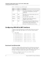
Page 17: ...e 1 1 ADSL 48 port Annex A LIM All status lights illuminate briefly upon startup or restart then remain dark until the module passes its power on self test POST When the module passes the POST and becomes operational the ACTIVE light illuminates It is the only light that is on during normal operation Table 1 1 explains the ADSL 48 port Annex A status lights ...

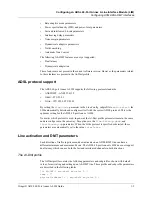
Page 18: ...99 00 27 37 shelf 1 slot 14 11 1 14 11 Overview of the Al Dmt profile Various discrete multitone DMT standards define the fast and interleaved data latencies for each direction upstream and downstream of ADSL transmission In the Stinger Al Dmt profiles you set parameters to specify the data rate signal quality and power and data delay of the interface The Stinger unit references these parameters i...

Page 19: ...uto select the LIM automatically detects and configures itself with the correct ADSL protocol This is the optimum setting for the ADSL 48 port Annex A LIM No matter which protocol is used in general the Al Dmt profile parameters remain the same and are configured in the same way Exceptions are the line latency down and line latency up parameters When the G lite protocol is specified or detected th...

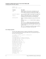
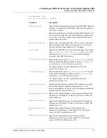
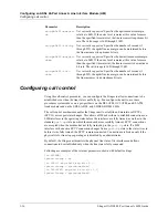
Page 20: ...default 20 db upstream start bin 6 upstream end bin 31 downstream start bin 32 downstream end bin 255 loop back none bit swapping no Parameter Description name Specifies the name of the interface The default value is the interface address in shelf slot port format for example 1 2 3 but you can assign a text string of up to 16 characters physical address Specifies the physical address of the interf...

Page 21: ...alue is interleave for G lite and fast for all other line protocols For related settings see Fast and interleaved bit rate parameters on page 1 10 line latency up Specifies the latency path fast or interleave to be used for upstream data transport Default value is interleave for G lite and fast for all other line protocols For related settings see Fast and interleaved bit rate parameters on page 1...

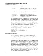
Page 22: ...default and operator controlled Automatic at startup rate adaptation means that the rate is selected during the training startup process The line initializes at a minimum specified bit rate and target noise margin If the line fails to achieve the minimum bit rate in either direction it cannot start and it sends a message that the requested bit rate was too high If the line can support a bit rate t...

Page 23: ...ectral density parameter specifies the PSD allowed on the line at the transmitter output expressed in dBm Hz It is defined for the downstream direction only with a valid range of 34 through 52 in even number increments If you lower the value from its default value of 40 the line consumes less power but also has a lower capacity Increasing the value can boost the PSD to achieve a higher capacity Fo...

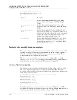
Page 24: ... and downstream traffic must use the same channel in AL DMT any shelf any slot 0 fast path config min bitrate up 128 min bitrate down 128 max bitrate up 1000 max bitrate down 8000 planned bitrate up 512 planned bitrate down 1000 For optimum performance under most conditions when using the 48 port Annex A LIM fast path bit rates should be configured as shown in the following example which shows how...

Page 25: ... rate for upstream traffic from 0Kbps through 1024Kbps When the automatic rate adaptive mode is in use the line initializes at this upstream rate or fails to initialize The default value for the ADSL 48 port Annex A LIM is 128Kbps Note Not configured for operator controlled rate adaptation min bitrate down Specifies the minimum bit rate for downstream traffic from 0Kbps through 8192Kbps When the a...

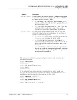
Page 26: ... a 48 port Annex A LIM in slot 2 admin read al dmt 1 2 1 AL DMT shelf 1 slot 2 1 read admin set interleave path config max bitrate up 1280 admin set interleave path config max bitrate down 12480 admin set interleave path config min bitrate up 32 admin set interleave path config min bitrate down 32 admin write planned bitrate up Specifies the constant bit rate for upstream traffic when operator con...

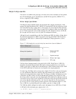
Page 27: ... power adjustments The target noise margin parameter is supported by the ADSL 48 port Annex A LIM The minimum noise margin and maximum additional noise margin parameters are not used by ADSL 48 port Annex A LIMs and are not detailed here Consult documentation for the ADSL G lite LIM for additional information about setting the noise margin parameters On many loops the Stinger unit uses large power...

Page 28: ...ifies the upstream noise margin relative to 0dB that must be present before the line can initialize successfully and rate adapt during normal operations The valid range is 0dB through 31dB with a practical limitation of 15dB set by the modem software The default for the ADSL 48 port Annex A LIM is 6dB target noise margin down Specifies the downstream noise margin relative to 0dB that must be prese...

Page 29: ...hift int down 0 ra upshift margin up 0 ra upshift int up 0 ra upshift margin down 0 ra upshift int down 0 Parameter Description ra downshift margin up Not currently supported Specifies the upstream noise margin relative to 0dB If the noise level remains at this value for more than the specified time interval the line reduces its upstream bit rate The valid range is 1dB through 31dB ra downshift in...

Page 30: ...ing or is disabled by an administrator By default the Stinger unit monitors the physical line state of its interfaces and allows connections to be established only when the line state is fully connected Following are examples of the relevant parameters shown with default settings in SYSTEM ignore lineup no in SDSL any shelf any slot 0 ignore lineup system defined in DS3 ATM any shelf any slot 0 ig...

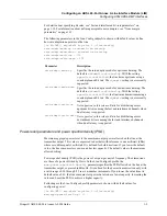
Page 31: ...e following values no the default The Stinger call control mechanism allows calls to be established when the line state is up and disallows calls when the line state is down yes The Stinger call control mechanism ignores the line state and allows calls to be established on a port as long as the specified slot is operational and the specified port is enabled ignore lineup In a Line profile specifie...

Page 32: ...et line config rate adapt mode down operator controlled admin set fast path config planned bitrate up 56 admin set interleave path config planned bitrate down 1500 admin write AL DMT shelf 1 slot 3 4 read The following commands configure the interface to automatically select the best possible rate at startup time They specify a possible upstream bit rate range of 56Kbps through 256Kbps and a possi...

Page 33: ...e might experience interference when the station resumes transmitting Selective bin loading enables you to mask the interfering frequency by disabling the Stinger frequency bin that corresponds to it You can also use selective bin loading to mask intermittent noise from other sources in a particular bundle from the central office Once you identify the interfering frequency you can disable the nece...

Page 34: ...per bin 14 bin loading yes yes yes yes yes yes yes yes yes yes yes yes yes yes yes yes in ADSL BIN LOADING default new changed admin set bin loading 149 no admin write in ADSL BIN LOADING default new changed name default bits per bin 14 bin loading yes yes yes no yes yes yes yes yes yes yes yes yes yes yes yes admin Bin 149 changed to NO Checking status of ADSL DMT interface The system creates a r...

Page 35: ...te Indicates the overall state of the line Possible values are as follows does not exist Link is not physically present on board disabled Line is disabled active Multipoint is established spare physical address Indicates the shelf slot and port number of the spare redundant LIM sparing state Indicates the state of the redundancy function If redundancy is not enabled sparing none is the value If sp...

Page 36: ...sage gives the reason loopback Interface is in special loopback test mode up stream rate fast Indicates the upstream data rate in bps when latency is fast Zero means that latency is set to interleave or the data rate is unknown down stream rate fast Indicates the downstream data rate in bps when latency is fast Zero means that latency is set to interleave or the data rate is unknown up stream rate...

Page 37: ... 0 far end hec 0 received rs blcks 104073 transmitted rs blocks 416772 ansi adsl ver Indicates the supported issue of the ANSI T1 413 standard Issue 2 hardware ver Indicates the hardware version of the ADSL modem modem hw State Indicates the state of the interface after initialization Valid values are init ok all is well bad sdram bad cache or bad cache sdram The last three values imply memory pro...

Page 38: ...icates current downstream attenuation in dB output power down Indicates current downstream aggregate power level in dBm noise margin up Indicates current upstream noise margin in dB attenuation up Indicates current upstream attenuation in dB output power up Indicates current upstream aggregate power level in dBm near end fec Indicates forward error correction FEC errors detected by the COE ADSL tr...

Page 39: ...s dvOp dvUpSt dvRq sAdm nailg Line 1 4 1 Up Idle UP UP 00151 Line 1 4 2 Up Idle UP UP 00152 Line 1 4 3 Up Idle UP UP 00153 Line 1 4 4 Up Idle UP UP 00154 Line 1 4 5 Up Idle UP UP 00155 Line 1 4 6 Up Idle UP UP 00156 Line 1 4 7 Up Idle UP UP 00157 Line 1 4 8 Up Idle UP UP 00158 Line 1 4 9 Up Idle UP UP 00159 Line 1 4 10 Up Idle UP UP 00160 Line 1 4 11 Up Idle UP UP 00161 ...

Page 40: ......

Page 41: ...in behind or next to it in place of a line protection module LPM All other LIMs must use an LPM with port redundancy LPM RP for line protection Note Some older Stinger systems are equipped with an interface redundancy module IRM located behind the spare LIM and LPMs with redundancy LPM R located behind the LIMs to be backed up In this case additional configuration steps might be needed For more in...

Page 42: ...reestablished on the spare secondary LIM When the redundancy function is disabled the spare LIM is deactivated Its logical connections are terminated and reestablished on the primary LIM Figure 2 1 illustrates LIM redundancy for a failed SDSL LIM in slot 4 of a Stinger FS chassis A Stinger LS chassis has its LPMs and PSMs or CLT modules next to its LIMs rather than behind them Figure 2 1 LIM redun...

Page 43: ...09 shelf 1 slot 16 0 The spare ADSL LIM has the following profile admin read lim sparing config 1 14 0 LIM SPARING CONFIG shelf 1 slot 14 0 read Parameter Specifies spare slot type Type of spare LIM installed in the slot This value is automatically detected and set by the software when the Stinger powers up sparing mode Enable disable redundancy You can enable two LIM redundancy modes The inactive...

Page 44: ... sparing mode parameter to manual To disable manual redundancy set the sparing mode parameter to inactive If manual redundancy is currently in use setting the parameter to inactive causes the spare LIM to become inactive again terminating its connections and then reestablishing them on the primary LIM that was replaced For example suppose that the SDSL LIM in slot 4 fails see Figure 2 1 To enable ...

Page 45: ... though the physical port switchover is successful Following is a listing of an Auto LIM Sparing Config subprofile with all parameters set to their default values in LIM SPARING CONFIG auto lim sparing config lim sparing config 1 active yes error averaging period 10 error threshold 100 up down threshold 3 modem failure threshold 12 Parameter Specifies active When redundancy mode is set to automati...

Page 46: ... Sparing Config subprofile for the LIM in slot 1 Note that the active parameter is set to yes Because this is the default value for all seven slots you do not have to set it unless you have previously changed it 2 Set the redundancy mode admin list in LIM SPARING CONFIG shelf 1 slot 15 0 physical address shelf 1 slot 15 0 spare slot type sdsl atm card sparing mode inactive spare slot number slot 1...

Page 47: ...PM Rs or LPM RPs installed in the slots behind or next to them When the profile is created the software automatically assigns a value to the spare slot type and spare slot number parameters For example if a Stinger has an SDSL LIM and an IRM installed in slot 16 and it also has an SDSL LIM with an LPM R installed in slot 4 you must first create a LIM Sparing Config profile for slot 16 admin new li...

Page 48: ...ring state sparing none Parameter Indicates spare slot type Shelf slot and port number of the spare LIM sparing mode State of the redundancy function If redundancy is not enabled sparing none is the value If redundancy is enabled and the LIM slot is a primary LIM the value can be primary active or primary inactive If redundancy is enabled and the LIM slot is the secondary spare LIM the value can b...

Page 49: ...PM 3 0 Empty IRM LPM 4 92 48 port Enhanced LPM 5 0 Empty IRM LPM 6 0 Empty IRM LPM 7 0 Empty IRM LPM 10 0 Empty IRM LPM 11 0 Empty IRM LPM 12 0 Empty IRM LPM 13 0 Empty IRM LPM 14 93 Path Selector Module PSM 15 0 Empty IRM LPM 16 94 Copper Loop Tester CLT Midplane sparing bus usage 4 4 3 2 1 8765 4321 0987 6543 2109 8765 4321 0987 6543 2109 8765 4321 XXXX XXXX XXXX XXXX XXXX XXXX Configuring LIM p...

Page 50: ...cular number at a time For example suppose port 1 on an SDSL LIM fails and is replaced As long as redundancy is active on that port no other failed SDSL or ADSL port 1 on that unit can be replaced by a spare LIM port For example port 2 on an ADSL LIM in slot 1 can be backed up by port 2 of the spare ADSL LIM in slot 14 A subsequent failure of port 6 on an SDSL LIM in slot 4 can be backed up by por...

Page 51: ... inactive again terminating its connections and then reestablishing them on the primary LIM port that was replaced For example suppose a Stinger FS is equipped with an ADSL LIM in slot 1 and an SDSL LIM in slot 4 Spare LIMs are located in slots 14 and 16 respectively Port 2 fails on the ADSL LIM and port 6 fails on the SDSL LIM To provide redundancy for these ports proceed as follows 1 Activate re...

Page 52: ...ess by resetting the system or by setting the sparing mode parameter to inactive and then back to automatic The parameters used for automatic LIM port redundancy are found in the Auto LIM Sparing Config subprofile of the LIM Sparing Config profile for the spare LIM of the same type For example suppose you want to set up automatic port redundancy for port 1 in an SDSL LIM in slot 5 with an error th...

Page 53: ... manual sparing change time 309108872 sparing change counter 1 Parameter Indicates spare physical address Shelf slot and port number of spare LIM sparing state State of the redundancy function If redundancy is not enabled sparing none is the value If redundancy is enabled and the LIM slot is a primary LIM the value can be primary active or primary inactive If redundancy is enabled and the LIM slot...

Page 54: ......

Reviews: