background image


#" !     " ! # $ $ !!# 

3

* ++ ' #(% ,#  -,)-,

!! -,,('  + (' ,$& -',$% ,# %*&

  )+ "$'
 +$'"%  $'$,(* (** +)('$'" /$,# ,#  -** ', + ,,$'" * &$'+

!%+#$'"

4

* ++ ,#  -,)-,

!! -,,(' ,( +*(%% ,#*(-"# ,# (&&-'$,$('

(),$('+ ,() ,( (,,(& # ,$& 1(- )* ++ ,# -,,(' ,#    )+ '

,#  ' 0, $'$,(* !%+# +


5

* ++ ' #(% ,#  -,)-,


' -,,(' -',$% ,#  %*&   )+ ,( + % , '

+.  (&&-'$,$(' (),$(' $%-* ,( * % + ,# -,,(' $&& $, %1

!, * ,#   ) /$%% -+ ,#  ,( (*, ,# + ,-)

6

* ++ ,#  -,)-,


' -,,(' "$' ,( * ,-*' ,#   ,( (*&% (


$,# ,#    *$% (&&-'$,$('+ $'  '- 1(- ' .$ / (* + % , 

(&&-'$,$(' &( + - *, + '  ('!$"-*,$('+ ( #'"  (* $+)%1

,# -** ', (&&-'$,$('+ ('!$"-*,$('

1

('' , ,#   + *$% )(*, ,(  .$ ( &('$,(* /$,#  + *$% $', *!  (* ,(

1(-* (&)-, *+ + *$% )(*, ! 1(- *  -+$'" +#-,(/' +(!,/*  ,#  

+#(-% %* 1   ('' ,  ,( 1(-* (&)-, *

2

 , 1(-* , *&$'% +( ,#, $, &,# + ,#  - *,  (! ,#   -+-%%1

 -  $,+ ( )*$,1  +,() $,  ! * ,( 1(-* , *&$'% (*

() *,$'" +1+, & (-& ',,$(' !(*  ,$%+ (' ('!$"-*$'" 1(-* , *&$'%

(&&-'$,$(' + ,,$'"+

3

, ,#  , *&$'% )*(&), )* ++

-',$% ,#   *$%

(&&-'$,$('+  '- )) *+

Summary of Contents for Uninterruptible Power Systems 3000 VA

Page 1: ... ...

Page 2: ... E 0 0 0 0 ...

Page 3: ... 0 0 ...

Page 4: ... ...

Page 5: ... Quick Start 1 Battery Module UPS Module Bypass Distribution Module BDM 60 Hz 2 Bypass Switch NORMAL Position 3 Battery Breaker I O ON OFF I O ON OFF I ON ...

Page 6: ... 4 5 6 ...

Page 7: ... 1 Bypass Isolation Module BIM 50 Hz Battery Module UPS Module 2 Bypass Switch NORMAL Position 3 Battery Breaker I O ON OFF I O ON OFF I ON ...

Page 8: ... 4 5 6 ...

Page 9: ...1 5 0 1 11 5 0 1 4 1 0 3 0 0 01 2 1 0 7 17 12 3 1 0 0 9 2 19 1 10 4 02 1 1 01 26 0 2 66 1 10 0 2 1 0 2 8 2 0 1 0 0 2 1 07 10 1 0 1 11 5 2 1 1 1 01 1 1 0 01 1 501 0 1 2 1 1 02 501 0 1 2 1 4 1 5 00 2 01 1 01 1 4 1 5 00 2 1 12 2 0 1 0 1 1 0 ...

Page 10: ... 1 0 1 0 ...

Page 11: ... Introduction 3 1 3 1 1 1 0 3 0 3 1 4 1 3 3 1 3 0 1 1 1 1 0 3 0 1 2 0 1 1 3 3 3 3 3 3 3 0 3 1 3 0 1 0 1 2 3 3 3 0 3 1 ...

Page 12: ...rement this is the typical relationship between watts and voltĆampere ratings in most computing equipment If the rating is in amperes or amperes max multiply by the input voltage to obtain the VA requirement 3 Add all of the resultant VA ratings together to obtain the total load requirements of the equipment to be protected see Figure 2 3 COMPUTERS 3 MONITORS EXTERNAL MODEM 3 x 200 WATTS x 1 4 840...

Page 13: ... ...

Page 14: ... ...

Page 15: ... Safety Warnings 0 3 0 3 1 3 3 3 0 0 0 1 3 0 3 2 1 2 0 3 3 3 2 3 2 3 1 3 0 1 1 1 1 1 1 1 1 0 3 0 0 3 1 4 41 3 3 0 0 2 _ _ 1 2 0 3 2 0 1 0 3 3 1 1 0 1 1 1 3 ...

Page 16: ... 1 132 43 2231 2 15 1 11 3 1 21 1 11 3 23 33 1 1 1 5 2 5 3 1 2 5 3 21 4 1 1 1 2 5 127 1 33 1 1 2 3 3 1 5 1 1 231 1 20 1 1 1 4 3 5 2 231 2 127 1 1 33 1 1 33 1 1 20 1 1 4 2 33 2 1 1 33 1 1 1 1 2 1 2 2 23 31 73 1 2 3 1 4 5 1 7 123 3 3 14 4 3 1 2 3 1 31 5 3 20 3 1 3 1 3 31 3 32 5 1 3 4 2 2 1 2 4 2371 1 31 1 3 23 3 3 5 1 2 3 2 2 1 31 13 22 20 3 1 31 1 3 5 2 231 2 3 3 1 127 3 5 1231 2 2 733 2 4 1 23 1 3...

Page 17: ...2 0 1 1 0 1 5 00 0501 7 02 0 3 01 9 0 0 511 0 3 0 01 9 0 2 0 0 9 05 0 5 00 0501 7 02 0 5 1 1 3 0 01 9 0 2 0 0 9 05 0 6 3 1 1 0 2 1 4 2 1 3 3 6 2 4 11 2 3 3 1 0 0 4 3 6 0 3 3 10 2 101 0 1 4 6 11 1 2 01 4 6 4 2 3 24 10 3 0 1 6 3 1 6 11 2 13 1 1 6 2 0 01 4 1 4 00 01 3 0 0 1 1 11 1 322 11 2 1 1 11 3 1 51 0 0 3 2 2 1 01 1 6 10 2 1 1 1 1 100 2 1 6 4 1 3 1 0 0 3 0 0 1 0 3 1 1 1 1 4 1 1 0 4 4 1 0 1 3 0 6 ...

Page 18: ... 3 3 6 1 0786442 3 2 6 3 2 11 25B6 3 44 4 3 438 8 447 24 8 45 2 3 6 3 2 8 6 3 55 6 8996 3 3 3 2 00 1 0 6 0 6 3 446 69 0 6 3 9 8E7 0 1 6 45 8 3 1 086 7 741 8 446 3 3 43 6 1 3 78 00 6 9 8 4 3 438 8 447 1 3 33 6 8 55 6 8 446 1 3 8 3 8 46 8 69 08 2 6 348 3 8 9 8 4 6 4 3 438 8 4 3 45 18 43 6 786442 78 3 33 6 1 78 3 7 0 1 6 46 8 3 6908 43 8 3 3 4 3 446 5 77 7 78 2 3 2 8 78E 6 9 8 3 3 24 8 4 6786442 1 3 ...

Page 19: ...7A1 03A7 6 77 _ 7 9 77 7 1 267 66 2 2 66 0 6 0 32 67 7 5527 6 6 178 2 2 72 81 21 7 77 1 0 32 67 7859 0 2 78 6 1 C 77 67 6 1 7 7 67 77 67267 16 19 6 7 1250 7 2 27860 5 6 7 9 7 9 7 77 1 7 0 1 C 77 1 8 2678 2 7 17A 1 7 1 1 0 982729 57 7 0 03 5 9 57 3 672 1 7 7 2 0 1 6 7 77 67267 77 1 6 7 9 C 77 1 9 57 7 1 5 67 6 6 26 9 55 1 6 11 7 5527 6 6 178 23 672 26 7 7 77 1 32 6 7A67 3 7 A 6 6 7 0 A6 820 221 77 ...

Page 20: ... 1 09 1 1 1 0 0 1 0 09 9 0 1 1 0 0 0 1 1 0 9 0 9 6 1 0 1 1 0 1 0 1 6 0 9 0 6 0 9 1 1 0 9 0 1 0 1 1 0 1 09 1 6 0 9 01 0 1 09 0 9 0 09 1 0 1 0 9 01 0 0 9 _ _ 10 6 3 09 1 1 1 0 8 3 2 0 1 3 0 0 0 1 0 1 0 1 6 0 9 1 09 0 1 09 09 0 13 0 8 0 0 0 13 7 1 0 1 0 6 0 0 0 09 1 09 09 6 0 0 0 9 8 0 1 0 0 12 6 80 1 09 0 0 6 10 0 1 0 1 0 1 0 9 0 1 0 8 0 9 0 0 0 1 9 3 1 1 9 9 1 5 0 1 0 0 1 0 1 0 1 0 1 0 9 0 0 0 9 09...

Page 21: ...4 7 4 3 30 5 315 3 33 34 44 2 3 6 2 2 3 80 2 C 44 2 C 2 7 43 5 2 5342 4 2 42 94 34 D2 54 5 5 3 5 842 4 3 52 3 4 6 27 3 3 2 4 3 3 34 0 4 3 4 2 4 42 6 2 2 4 4 234 34 3 D2 6 27 4 7 2 3 0 4 6 2 2 4 4 34 5 3 5 2 2 4 5 6 2 234 34 4 2342 3 54 D2 3 342 34 3 6 2 34 234 2 334 2 6 34 34 3 34 4 752 52 0 3 2 4 2 4 2E 3 342 34 3 6 27 2 E 2 42 3 2 5 6 22 2 3 52 5 4 42 24 2 0 2 452 5 5 4 5 4 4 34 2 4 54 34 6 2 3 ...

Page 22: ...6 3 1 3 23 3 6 1 1 7 22 723 3 235 1 1 3 3 42 22 1 2 3 1 1 42 26 2 231 1 2 3 22 6 13 16 3 1 3 23 3 6 1 3 43 04 23 14 23 3 3 4 3 433 1 8 1 1 8 43 8 5 22 1 334 3 3 1 14 23 3 3 4 3 5 2 33 1 22 1 2 3 1 1 2 2 22 331 423 1 5 3 3 11 3 543 13 1 4 3 22 15 1 2 3 23148 33 1 5 22 1 2 3 3 11 33 1 1 04 2 3 2 3 3 1 1 1 3 2 2 8 04 23 14 23 3 3 4 3 3 4 3 1 43 33 1 1 2 42 3 22 411 3 2 1 88 3 04 14 23 3 3 4 3 3 4 3 3...

Page 23: ... _ ...

Page 24: ... skade på utstyr Sjekk også at det finnes overstrømvern for vekselstrømkontakten under installeringen Sjekk at støpselet er ført helt inn i stikkontakten Bruk kun en enĆfaset treĆtrådet jordet vekselstrømkontakt For å redusere fare for brann eller elektriske støt bør denne UPS en installeres i et innendørs miljø med kontrollert temperatur og luftfuktighet som er fritt for ledende forurensende stof...

Page 25: ... 0 7 9 48 1 2 2 1C2 6 1 2175 21 7 2 80 217 0 17 EC2 255 17 7 51 81 6 6 E 6 7 5 6 2 1 2L 6 12 2 2 B 5 6 2 3 26C2 48 1 2 3267 6 A 0 6 81 5 28 1 48 6 7 5 6 75I 72 5 2 F 35 8 A 3 26 2 26 32 6 5 75 0 0 17 7I 2 7 620 17 2 2 0 17 EC2 F75 251 2 20 2 67 2 2 0 18 785 2 25 2 20 6 63 EJ 6 2 17 51 7 21 75 2 57 48 L6 48 720 3 5 2 0217 25 2 20 67 6 0 60 6 63 EJ 6 0 9 7 5 026 2 6 8 48 3 0 172 25 167 EC2 57 48 L6 ...

Page 26: ... 1 1 1 3 1 0 0 3 6 0 2 1 2 1 01 3 00 1 7 0 1 1 9 0 01 0 5 00 0 0 1 0 1 9 0 2 1 0 0 1 1 3 0 21 0 0 01 0 5 00 0 0 1 0 1 2 1 0 0 49 3 1 2 0 2 1 0 0 1 1 3 0 0 21 0 01 02 01 1 1 1 0 0 0 5 0 3 1 8 0 6 0 01 0 1 0 2 0 1 2 0 0 0 1 0 2 2 0 1 1 1 2 1 01 1 0 01 2 0 0 1 0 0 0 0 0 0 1 0 2 1 02 1 0 0 0 0 0 28 0 0 0 2 0 1 0 1 1 0 01 1 02 2 1 1 0 0 0 2 0 18 2 0 0 1 1 0 2 018 1 2 02 01 1 1 2 0 1 0 2 5 2 2 4 1 2 0 4...

Page 27: ... 0 2 92 0 9 1 0 0 5 0 9 6 0 0 4 5 1 0 1 7 8 0 0 0 0 9 3 9 2 0 0 5 0 3 0 6 0 0 3 0 3 0 0 0 _ _ 0 0 0 2 1 52 0 5 9 0 0 3 0 0 6 0 5 3 0 0 0 0 0 3 0 6 4 0 0 5 0 0 0 7 0 0 5 0 5 1 4 0 3 0 0 0 6 3 9 2 0 5 0 3 0 2 9 0 5 0 ...

Page 28: ...44 4 3 6 231 33 8 2 6 7 342 3544 4 6 34 4 0 34 4 0 420 2 44 0 4 4 2 4 3 54 6 544 4 6 34 44 3 4 02 4 6 7 342 3544 42 2 3 2 3 2 42 3 34 4 2 0 44 34 2 4 0 53 2 4 1 2 452 0 5 4 5 4 4 2 0 420 2 0 2 202 2 2 0 2 6 4 1 2 452 2 6 234 _ 53 6 4 542534 2 6 44 2 6 5 4 5 4 4 7 2 024 3 2 4 2 1 3 44 4 2 024 3 2 43 02 2 4 0 2 3 54 542534 2 44 6 2 334 4 2 4 0 34 2 0 2 3 2 3 2 4 2 2 4 404 542534 30 3 54 43 4 544 4 1...

Page 29: ... ...

Page 30: ... ...

Page 31: ... life For longer term storage energize the UPS and battery module for approximately 8 hours every 90 days in order to maintain battery charge Whenever the units are not energized make sure the circuit breaker on all battery modules is returned to the OFF O position see Figure 5 on page 26 UPS applications requiring a serial interface or standard LAN interface may connect directly to the 25Ćpin UPS...

Page 32: ...21 4 1 1 2 7 2 2 Comcode PEC For 3B2 systems use 406707737 24024 For all other systems use 407691401 24433 1 1 2 0 4 1 1 2 1 1 2 1 0501 1 1 0 1 1 0 3 5 1 2 1 0 7 1 3 1 0 21 21 0 0 1 2 1 1 5 00 2 0 3 7 6 01 21 2 7 6 0 1 2 4 1 2 1 4 1 5 00 2 0 3 1 5 00 12 1 1 02 0 4 1 5 2 2 1 3 4 1 1 0 3 1 2 0 5 00 01 21 2 0 3 0 21 21 0 1 4 2 1 01 1 4 1 5 00 2 1 1 2 1 1 1 1 02 1 0 4 3 1 1 4 5 1 02 1 1 1 0 2 1 1 1 11...

Page 33: ...s Distribution Module BDM 60 Hz UPS Module Stacking Module Cover the smaller flanges without holes face toward the front 1 4Ć20 x 1 2 Screws 1 4Ć20 x 1 2 Screws Battery Module Caster Base Floor Mounting Plate ...

Page 34: ...Module Bypass Isolation Module BIM 50 Hz Stacking Module Cover the smaller flanges without holes face toward the front 1 4Ć20 x 1 2 Screws 1 4Ć20 x 1 2 Screws Battery Module Caster Base Floor Mounting Plate ...

Page 35: ... 2 A WALL 11 0I minimum recommended for cabling 16 16I Unit Depth 10 0I 12 5I Unit Width 6 5I 3 0I 3 5I Seismic Mounting Holes FRONT B 3 ...

Page 36: ...PS Module Breaker Tie Circuit Breaker Battery Module External Battery Connector Battery Cord Bypass Switch Load Circuit Protectors Input Circuit Protector Battery Connector Power Output Receptacle Power Input Connector Serial Port YĆCord Tie Wrap Mounts REPO Receptacle ...

Page 37: ...dule Battery Connector Power Input Connector Serial Port External Battery Connector Battery Cord BIM 50 Hz YĆCord Utility Input Connector Output Breaker Power Output Receptacles Bypass Switch I I I Input Breaker Input Circuit Protector Power Output Receptacle Tie Wrap Mounts ...

Page 38: ... 0 10 10 10 0 0 0 0 0 3 0 1 0 0 0 3 1 0 12 1 0 7 0 5 1 0 0 3 0 0 3 1 1 13 5 0 0 0 1 1 5 0 0 0 3 1 0 7 0 0 0 0 1 0 0 0 I 14 5 1 5 1 1 0 1 0 0 1 0 0 5 1 5 1 3 0 0 15 40 3 0 10 1 1 1 0 0 0 3 10 10 0 0 5 1 16 1 0 0 0 0 5 0 1 3 1 0 1 0 0 0 3 10 10 0 0 5 1 0 0 0 3 0 0 1 0 4 0 5 3 1 0 0 0 0 17 5 1 1 0 5 3 7 3 0 3 0 0 1 0 6 0 0 18 0 0 0 0 0 6 3 0 5 1 0 01 1 ...

Page 39: ... 19 20 Terminal Block Access Cover Bypass Switch Input Breaker Access Cover Screw Access Cover Screw Access Cover Screw 1 2I Input Conduit Access 1 2I Output Conduit Access ...

Page 40: ... Ground Line 1 Line 2 Neutral Ground Neutral Line 2 Line 1 120V 208V 240V Input Output Ground Line Neutral Ground Neutral Line 220 230 240V Input Output ...

Page 41: ... Ground 1 22 12 AWG 0 34 4 mm2 3 5 5 3 lb in 5 6 6 8 lb in L1 2 lb lb L2 Neutral 3 18 10 AWG 2 3 5 5 3 lb in 4 5 7 0 lb in Output L1 5 0 75 6 mm2 3 5 5 3 lb in 4 5 7 0 lb in L2 Neutral 6 Ground 8 22 12 AWG 2 3 5 5 3 lb in 5 6 6 8 lb in No Connection 4 7 0 34 4 mm2 3 5 5 3 lb in 5 6 6 8 lb in Use 16ĆAWG 1 5 mm2 75_C copper wire minimum 23 2 0 24 3 3 1 5 1 1 4 25 4 1 3 1 5 1 0 3 1 3 2 1 1 1 1 H 1 1 ...

Page 42: ...le for Conduit Power Cable Terminations Tightening Torque Wire Function Terminal Position Terminal Wire Size Rating Entrelec Phoenix Contact REPO L1 TB1Ć4 lb lb L2 TB1Ć5 12Ć22 AWG 4Ć0 mm2 3 5 5 3 lb in 5 6 6 8 lb in Ground TB1Ć6 Suggested wire size is 18ĆAWG 0 75 mm2 75_C copper wire minimum NOTE The REPO function activates when L1 and L2 are shorted together ...

Page 43: ...8 60ĆHz BDM 208 120 240 208 60ĆHz BDM 208 120 208 60ĆHz BDM 240 120 240 Set to 220V for 110 220V BDM output Set to 230V for 115 230V BDM output Set to 240V for 120 240V BDM output 60ĆHz BDM 240 120 Set to 220V for 110V BDM output Set to 230V for 115V BDM output Set to 240V for 120V BDM output 50ĆHz BIM 208 Model 2500 only 208 50ĆHz BIM 220 220 50ĆHz BIM 230 230 50ĆHz BIM 240 240 The UPS output vol...

Page 44: ... 4 5 OVERLOAD 1 2 3 OUTPUT ON 220V 230V 240V 208V 6 7 8 9 ...

Page 45: ... ...

Page 46: ... ...

Page 47: ... On Indicator Unlit Amber Green Flashing Input On Indicator NjLoad or Battery Conditions Indicators I I I Output On Button UPS on load online On Battery or Bypass Indicator Output Off Button UPS off load offline OVERLOAD LOAD OR BATTERY CONDITIONS OUTPUT ON ON BATTERY OR BYPASS INPUT ON ...

Page 48: ...6 1 Rectifier Battery Circuit Breaker Battery Module Optional Battery Module Optional Battery Module EBC Battery Charger Input Plug EMI RFI Filter Input Circuit Breaker Inverter Bypass Load Relay UPS Load AC Input to BDM BDM UPS Load 2 1 1 2 1 0 1 1 0 50 1 1 15 20 5 1 1 1 2 1 0 2 OVERLOAD 1 2 3 OUTPUT ON ...

Page 49: ... battery recharges BATTERY ONLINE 75 CAPACITY REMAINS BATTERY ONLINE 50 CAPACITY REMAINS BATTERY ONLINE 25 CAPACITY REMAINS BATTERY ONLINE BATTERY ONLINE SHUTDOWN IMMINENT LOW BATTERY WARNING OVERLOAD 1 2 3 OUTPUT ON If battery capacity becomes low while in Battery Mode the I3 Indicator begins to flash and the Output On Indicator remains lit indicating approximately two minutes before UPS shutdown...

Page 50: ... 1 0 H H 1 H 1 H 0 0 2 1 0 1 1 1 0 1 0 1 0 1 0 0 1 1 1 1 1 ...

Page 51: ... 1 1 3 1 5 1 1 1 2 3 2 3 0 1 3 1 3 0 1 1 0 2 1 4 1 3 3 0 1 3 3 3 1 1 1 3 0 1 3 1 3 3 1 1 3 3 1 2 2 3 ...

Page 52: ... 3 4 5 6 BDM 60 Hz UPS Module Battery Circuit Breaker Battery Module Bypass Switch Battery Connector Power Output Receptacle Power Input Connector YĆCord ...

Page 53: ... 0 0 4 4 0 1 2 3 Bypass Module Model Number UPS Voltage Selection 4 3 4 3 4 3 4 3 0 0 0 0 0 0 4 3 0 0 0 0 0 0 4 3 2 4 3 4 3 4 3 0 0 1 0 1 4 ...

Page 54: ... 5 OVERLOAD 1 2 3 OUTPUT ON 220V 230V 240V 208V 6 7 8 9 ...

Page 55: ... Communication 0 2 0 2 0 2 2 1 4 3 1 0 H 0 H H 0 2 2 0 2 2 4 0 2 2 0 H 0 0 0 2 1 0 0 2 1 H 0 1 4 2 4 2 4 2 0 5 0 45 0 0 2 1 1 4 0 0 4 0 H 3 2 0 0 2 0 H 4 0 0 0 4 0 2 0 0 0 0 R R R ...

Page 56: ... Unlit Amber Green Flashing OVERLOAD I I I OUTPUT ON 0 Default 0 OVERLOAD I I I OUTPUT ON OVERLOAD I I I OUTPUT ON OVERLOAD I I I OUTPUT ON OVERLOAD I I I OUTPUT ON ...

Page 57: ... 3 4 1 0 5 1 6 1 1 1 1 1 1 1 2 1 1 1 1 1 1 3 ...

Page 58: ...L VT100 TERMINAL PRINTER DUMP LAN CONFIGURATION SET BAUD RATE QUIT WITHOUT SAVING NEW CONFIGURATION SAVE AND RESTART D DISPLAY CONFIGURATION Catalog D3023002202C New COMM ASCII Press space bar to continue Serial Version COMM mode Baud x100 LAN mode BP174C0998 3 05 Ser_Print 024 Novell New Baud New LAN 096 Novell Site Fault Detection Disabled ...

Page 59: ...bled active HIGH 12V SELECT CUSTOM LAN CONFIGURATION ENTER SELECTION B C Q TO QUIT THIS MENU Inverter shutdown control is enabled active LOW 12V Inverter shutdown control is disabled Instructions Choose the desired inverter shutdown function Warning It is recommended that this feature should not be used with normal RS 232 communications conflicts may occur ...

Page 60: ...UTIL_FAIL is active open LOW_BATT is active closed UTIL_FAIL is active closed LOW_BATT is active open UTIL_FAIL is active open LOW_BATT is active open TO QUIT THIS MENU Instructions Choose the desired contact configuration SELECT BAUD RATE 2 300 ENTER SELECTION 4 5 6 7 8 Q 1200 2400 4800 9600 19200 QUIT THIS MENU ...

Page 61: ... UPS Rear Panel Serial Port Detail Serial Port ...

Page 62: ...on Signal Name Pin No True Condition 2 4 40 8 4 20 8 205 06 44 29 1 07 44 29 03 205 06 5 4 0 0 3 44 29 03 5 4 0 0 3 5 4 07 44 29 03 205 0 54 07 04 03 4 6 0 4 07 44 29 03 4 6 0 4 44 29 03 4 6 0 4 205 6 6 03 44 29 4 49 52 03 91 33 03 07 44 29 07 44 29 03 205 ...

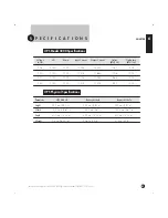
Page 63: ...A 14 42A 1081 1574 220 3000 2100 12 30A 13 64A 1006 1574 230 3000 2100 11 70A 13 04A 968 1574 240 3000 2100 11 30A 12 50A 923 1574 Parameter UPS Module Battery Module Bypass Module Height 252 mm 9 91 in 252 mm 9 91 in 252 mm 9 91 in Width 142 5 mm 5 61 in 142 5 mm 5 61 in 142 5 mm 5 61 in Depth 400 mm 15 75 in 400 mm 15 75 in 400 mm 15 75 in Weight 7 4 kg 16 25 lb 23 6 kg 52 lb 21 4 kg 47 lb ...

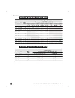
Page 64: ... 0A 14 4A 12 5A 12 5A 240 120 240 11 3A 12 5A 12 5A 12 5A 208 120 13 0A 25 0A 12 5A 12 5A 240 120 11 3A 25 0A 12 5A 12 5A 208 120 208 13 0A 12 5A 12 5A 14 4A 208 120 240 13 0A 12 5A 12 5A 12 5A 240 120 240 11 3A 12 5A 12 5A 12 5A 240 120 240 11 3A 12 5A 12 5A 12 5A Voltage In Out Input Current Output Current Total not to exceed 2100 Watts 3000 VA g Current IEC 320ĆC19 IEC 320ĆC13 Hardwired 220 220...

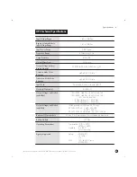
Page 65: ...le 2Ćmeter cord with L6Ć30P Outlets UPS Module IEC 320 1 Output Voltages and Outlets with BDM 120 208V L6Ć30R or L14Ć30R 4x5Ć15R 120 240V L6Ć30R or L14Ć30R 4x5Ć15R 120 L5Ć30R 4x5Ć15R 208V Hardwired 120 208V 240V Hardwired 120 240V Output Voltages and Outlets with BIM 208V available with Model 2500 only 220 230 240V 1 x IEC 320ĆC19 3 x IEC 320ĆC13 220 230 240V Hardwired 220 230 240V Batteries 10 pe...

Page 66: ... ...

Page 67: ... Troubleshooting 0 0 Unlit Amber Green Flashing Condition Possible Cause Action 0 0 0 0 0 0 0 0 0 0 0 0 ...

Page 68: ... ON 3 0 0 5 1 0 2 2 1 0 2 0 0 0 0 5 0 10 10 100 1 0 0 1 5 0 0 05 OVERLOAD I I I OUTPUT ON 10 05 2 0 1 5 10 0 2 0 2 3 0 10 05 1 0 0 0 0 1 0 1 0 0 0 1 0 0 OVERLOAD I I I OUTPUT ON 0 0 01 0 0 3 0 0 5 4 0 5 10 3 0 0 3 10 3 0 2 0 2 5 0 1 0 4 0 5 10 0 5 0 0 5 1 2 0 0 2 0 0 OVERLOAD I I 00 5 3 3 0 00 5 0 1 0 0 0 2 00 0 0 I OUTPUT ON 00 5 1 0 00 5 1 0 0 00 5 1 0 5 0 0 0 1 00 5 0 ...

Page 69: ... Action Possible Cause Condition OVERLOAD I I I OUTPUT ON 1 1 1 1 OVERLOAD I I I OUTPUT ON 1 1 1 1 0 1 1 1 1 1 1 1 1 1 H H H H H 1 H ...

Page 70: ...3 20 1 3 22 05 3 22 05 3 20 7 6 0 4 0 7 6 7 7 6 7 7 6 7 7 6 0 4 0 7 6 0 4 0 7 6 7 6 7 0 7 2 7 4 2 7 1 0 7 2 7 4 2 7 1 7 1 0 7 2 7 4 2 7 1 7 7 0 7 2 7 4 2 0 4 0 32 32 7 0 3 2 0 0 0 7 2 7 4 2 7 1 7 7 0 7 2 7 4 2 7 7 2 3 2 3 2 3 ...

Page 71: ... Index ...

Page 72: ... 0 0 0 0 0 0 0 ...

Page 73: ... 0 0 0 0 0 0 0 0 0 1 0 ...

Page 74: ... ...

Page 75: ...3 23 42 1 6 3 3 2314 3 4 8 42 3 1 1 3 1 4 3 2 1 3 3 2 04 3 1 2 3 1 2 8 3 42 3 1 1 6 2 3 42 1 6 1 04 1 3 11 3 3 3 1 1 3 2 6 7 2 41 3 2 1 22 4 1 2 9 22 1 1 231 3 2 231 43 1 3 2 41 3 2 3 6 2 2 2 22 1 4 3 23 5 1 3 3 2 1 4 3 8 42 1 3 1 1 6 2 3 42 1 8 1 04 1 3 3 3 241 2 32 3 3 1 6 3 1 8 6 3 3 6 1 3 5 2 4 1 3 5 04 3 2 1 42 6 3 13 5 3 32 1 3 5 4 1 3 5 1 3 3 31 3 3 38 1 3 1 38 2 5 4 1 04 23 1 1 4 32 6 3 1 ...

Reviews: