background image

LucidControl DI4DO4, User Manual (1.0) 


2022/02/03 

Page 12 of 47 


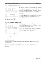
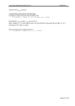
Fig. 4 Digital Input Channel Processing 
in Reflect Mode


In all modes the input values are captured and evaluated after a stable signal has been 
detected. 

3.1.3.1


Reflect Mode 

The reflect mode acquires the logical input value. 

Fig. 4 illustrates the processing of the digital input 
channels in reflect mode. 

After the rising edge of the input signal was detected 
and it remained stable for the interval T

Scan

 the input 

value is updated. 


In the case that a pulse of the input signal is shorter than 
T

Scan

, it is ignored and the input value does not change. 

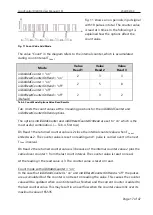
Fig. 5 shows this at the first pulse. The rising edge of the 
input signal starts the scan timer and the falling edge 
stops it (indicated by the gray T

Scan

 interval). 

The second pulse is longer than T

Scan

 and considered 

valid. The input value is updated. 


Filtering digital signals can be used in order to surpress instable signals (debouncing). It 
makes the detection of digital input signals more relyable. 

The scan interval T

Scan

 is configured by the parameter 

inDi0ScanTime

 (

 0)

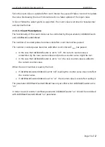
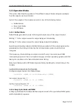
Fig. 6 illustrates the digital input signal and the inverted 
input value with configuration parameter 

inDi0Inverted


set to “on”.


Fig. 5 Reflect Mode Pulse Width


Fig. 6 Inverted Reflect Mode


Summary of Contents for DI4DO4

Page 1: ...LucidControl DI4DO4 User Manual 1 0 2022 02 03 Page 1 of 47 User Manual LucidControl DI4DO4 USB Module with 4 Digital Input and 4 Digital Output Channels...

Page 2: ...3 1 1 Real time Considerations 11 3 1 2 Input Signal Value Inversion 11 3 1 3 Operation Modes 11 3 1 3 1 Reflect Mode 12 3 1 3 2 Edge Detection 13 3 1 3 2 1 Rising Edge Detection Mode 14 3 1 3 2 2 Fal...

Page 3: ...Di0CountTime 36 3 4 2 Digital Output Channels 37 3 4 2 1 outDi1Value 37 3 4 2 2 outDi1Mode 38 3 4 2 3 Bit Parameter outDi1Flags 39 3 4 2 3 1 outDi1Inverted 39 3 4 2 3 2 outDi1CanCancel 39 3 4 2 3 3 ou...

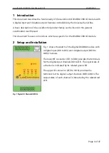
Page 4: ...on functions which are specific for the DI4DO4 USB IO module 2 Setup and Installation Fig 1 shows the sketch of the Digital DI4DO4 module with 4 digital input DI0 to DI3 and 4 digital output DO0 to D...

Page 5: ...l the following safety and maintenance information must be adhered The device must only be used for the intended purpose The device must not be used under the following conditions It is obviously dama...

Page 6: ...characteristic voltages for the different threshold levels Voltages below VLowMax result in a LOW value voltage higher than VHighMin in a HIGH value Because of the input hysteresis voltages between VL...

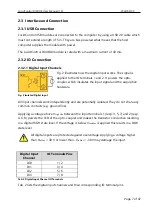
Page 7: ...and the acquisition hardware All input channels work independently and are potentially isolated They do not share any common contacts e g ground line Applying a voltage above VHighMin between the inpu...

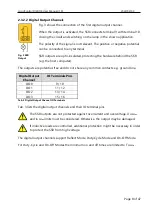
Page 8: ...are potential free and do not share any common contacts e g ground line Digital Output Channel IO Terminals Pins DO0 9 10 DO1 11 12 DO2 13 14 DO3 15 16 Tab 3 Digital Output Channel IO Terminals Tab 3...

Page 9: ...operating system ensures that the same serial port number is assigned to the module s after restart 2 4 2 Linux The module is immediately installed as dev ttyACMn device where n is a number referring...

Page 10: ...outputs LucidIoCtrl dCOM1 tL c0 1 2 3 4 5 6 7 r ENTER CH0 00 CH1 00 CH2 00 CH3 00 CH4 00 CH5 00 CH6 00 CH7 00 Linux Examples For all examples it is assumed that the module is connected to dev ttyACM0...

Page 11: ...teristics 3 1 2 Input Signal Value Inversion Digital input channels have an input signal value and a logical input value The input signal value is represented by the voltage applied to the input chann...

Page 12: ...signal is shorter than TScan it is ignored and the input value does not change Fig 5 shows this at the first pulse The rising edge of the input signal starts the scan timer and the falling edge stops...

Page 13: ...cannot be ensured that a task will continue to run within a specified interval USB is also no real time bus and limits the timing The following example explains how the edge detection mode can improve...

Page 14: ...al without the host computer being involved 3 1 3 2 2 Falling Edge Detection Mode The falling edge detection mode Fig 8 operates similar to the rising edge detection mode but triggers at high to low t...

Page 15: ...he input signal was detected In the case that the parameter inDi0Inverted is set to on TScan time starts when the falling edge of the input signal is detected Reading the input value in count mode ret...

Page 16: ...er counted pulses becomes valid after count interval TCount has passed In the case that inDi0AddCounter is set to off the current counter value is overwritten by the new counter value and previous cou...

Page 17: ...terOnRead are set to on which is the most useful combination Tab 4 first row On Read 1 the returned counter value is 2 since the internal counter value when TCount ended was 2 The counter value is res...

Page 18: ...ess to the logical output value In the case that outDi1Inverted is set to off output signal value inversion is disabled and the output signal values and logical output values are identical In the case...

Page 19: ...the output signal can be generated but the timing is limited by the communication protocol and the host computer This means e g that switching an output on and off every 1ms would need 1000 commands...

Page 20: ...e time period of the signal and can be configured by the IO Configuration Parameter outDi1CycleTime The IO Configuration Parameter outDi1DutyCycle defines the relation of the on time TOn and the off t...

Page 21: ...utput channel 4 for Duty Cycle mode LucidIoCtrl dCOM4 c4 soutDi1Mode dutyCycle ENTER Start processing of PWM signal for output channel 4 LucidIoCtrl dCOM4 c4 tL w1 ENTER By default the module is confi...

Page 22: ...ld is specified by the parameter outDi1OnHold Output Signal Value Inversion Fig 16 shows the output signal in case that the output signal inversion is enabled for the output channel outDi1Inverted set...

Page 23: ...ple Configure output channel 4 for On Off mode LucidIoCtrl dCOM4 c4 soutDi1Mode onOff ENTER By default TOnDelay and TOnHold are set to 1s After writing a 1 to the output value of channel 0 the output...

Page 24: ...0 DI1 1 DI2 2 DI3 3 DO0 4 DO1 5 DO2 6 DO3 7 Tab 5 IO Connections and Channel Numbers Tab 5 lists the digital IO channels Tab 2 Tab 3 and their channel numbers 3 3 1 SetIo This command sets one output...

Page 25: ...scription Channel Number of input or output channel Range 3 to 7 Value Type Value Type Supported Value Types Value Type Value Range Length Digital Logic Value 0x00 0 1 1 Byte Length Length of the Valu...

Page 26: ...Channels tL w Values Channels Comma separated list of channels e g c4 5 6 Values Comma separated list of values to set e g w1 1 0 LucidIoCtrl Command Line Tool Example Set output channel 4 to 1 output...

Page 27: ...nnel 7 Value Type Value Type Supported Value Types Value Type Value Range Length Digital Logic Value 0x00 0x00 oder 0x01 1 Byte Length Length of the Values in the Data Field One Value for each channel...

Page 28: ...annel Tab 6 lists the digital output channel modes and how the IO value is interpreted Tab 8 lists the digital input channel modes and how the IO value is interpreted Command GetIo Access Read Opcode...

Page 29: ...pe Value Range Response Len Digital Logic Value 0x00 0 1 1 Byte Digital Counter Value 0x0A 0 65 535 2 Bytes Response Frame Status LEN Data Field Status Length Value In case of successful execution the...

Page 30: ...cess Read Opcode 0x48 LucidIoCtrl Command Line Tool Call tL LucidIoCtrl d COMx c Channels tL r Channels Comma separated list of channels e g c0 1 7 Return List of values sorted from lower to higher ch...

Page 31: ...sing channel numbers 0 and 3 Value 0x01 OR 0x08 0x09 1 and 2 Value 0x02 OR 0x04 0x06 1 2 and 7 Value P1 0x02 OR 0x04 0x86 Value P1A 0x01 for channel 7 Value Type Supported Value Types Value Type Value...

Page 32: ...al LucidControl User Manual The DI4DO4 modules mixes input and output channels what made it necessary to rename parameter names and change parameter addresses 3 4 1 Digital Input Channels 3 4 1 1 inDi...

Page 33: ...dIoCtrl d COMx c Channel ginDi0Mode LucidIoCtrl Command Line Tool Example Set operation mode of input channel 0 to Count Mode and make the setting persistent LucidIoCtrl dCOM4 c0 sinDi0Mode count p EN...

Page 34: ...version of input channel 0 and make the setting persistent LucidIoCtrl dCOM4 c0 sinDi0Inverted on p ENTER Read input signal value inversion flag of input channel 0 LucidIoCtrl dCOM4 c0 ginDi0Inverted...

Page 35: ...ool Parameter Name inDi0ResetCounterOnRead Parameter Values on off Call Set LucidIoCtrl d COMx c Channel sinDi0ResetCounterOnRead Value p default Call Get LucidIoCtrl d COMx c Channel ginDi0ResetCount...

Page 36: ...canTime 1500000 3 4 1 5 inDi0CountTime This IO Configuration Parameter specifies the count time TCount of the digital input in Count Mode The count interval specifies the time during which pulses of t...

Page 37: ...meter outDi1Value Access Read Write Address 0x1800 Values Output Value Default Value 0x00 Parameter Type 1 Byte unsigned LucidIoCtrl Command Line Tool Parameter Name outDi1Value Parameter Values 0 1 C...

Page 38: ...eter Type 1 Byte unsigned LucidIoCtrl Command Line Tool Parameter Name outDi1Mode Parameter Values incactive reflect onOff dutyCycle Call Set LucidIoCtrl d COMx c Channel soutDi1Mode Value p default C...

Page 39: ...write sequence in order to prevent overwriting other bit parameters 3 4 2 3 1 outDi1Inverted This Bit Parameter configures the output signal value inversion Parameter outDi1Flags Access Read Write Add...

Page 40: ...channel 4 LucidIoCtrl dCOM4 c4 goutDi1CanCancel ENTER outDi1CanCancel on 3 4 2 3 3 outDi1CanRetrigger This Bit Parameter configures the on phase retrigger function of the output See the output modes...

Page 41: ...ter of output channel 4 LucidIoCtrl dCOM4 c4 goutDi1CycleTime ENTER outDi1CycleTime 1500000 Note Timing limits for TRes see 3 2 2 have to be considered 3 4 2 5 outDi1DutyCycle This IO Configuration Pa...

Page 42: ...NTER Read TOnDelay setting for output channel 0 LucidIoCtrl dCOM4 c4 goutD1iOnDelay ENTER outDi1OnDelay 520000 Note Timing limits see 3 2 2 have to be considered 3 4 2 7 outDi1OnHold This IO Configura...

Page 43: ...LucidControl DI4DO4 User Manual 1 0 2022 02 03 Page 43 of 47 Note Timing limits see 3 2 2 have to be considered...

Page 44: ...RIn 1 k Inputs Timing Characteristic TScan tMin TScan 1 s TCount 1 ms TCount 1 h Minimum pulse length tMin 100 s Maximum Frequency of Input Signal in Count Mode DC 50 2 000 Hz 20 DC 80 500 Hz Outputs...

Page 45: ...ight in total 120 g Assembly Rail Mount EN 50022 TS35 Protection Class DIN 40050 IP20 Module Indicators Operation and Error Indicator Communication Indicator Indicator Input Output State Enabled Disab...

Page 46: ...ol USB IO Module with 4 insulated 5V Input Channels and 4 Solid State Relay SSR Output Channels LCTR DI4 10 DO4 I LucidControl USB IO Module with 4 insulated 10V Input Channels and 4 Solid State Relay...

Page 47: ...ucidControl DI4DO4 User Manual 1 0 2022 02 03 Page 47 of 47 6 Document Revision Date Rev 2022 02 03 1 0 Initial documentation deciphe it GmbH Sch ferstr 5 87600 Kaufbeuren Germany www lucid control co...

Reviews: