LucidControl DI4DO4, User Manual (1.0)
2022/02/03
Page 7 of 47
2.3
Interface and Connection
2.3.1
USB Connection
LucidControl USB modules are connected to the computer by using a USB 2.0 cable which
must not extend a length of 5 m. They are bus powered what means that the host
computer supplies the module with power.
The LucidControl DI4DO4 module is rated with a maximum current of 40 mA.
2.3.2
IO Connection
2.3.2.1
Digital Input Channels
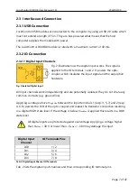
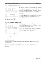
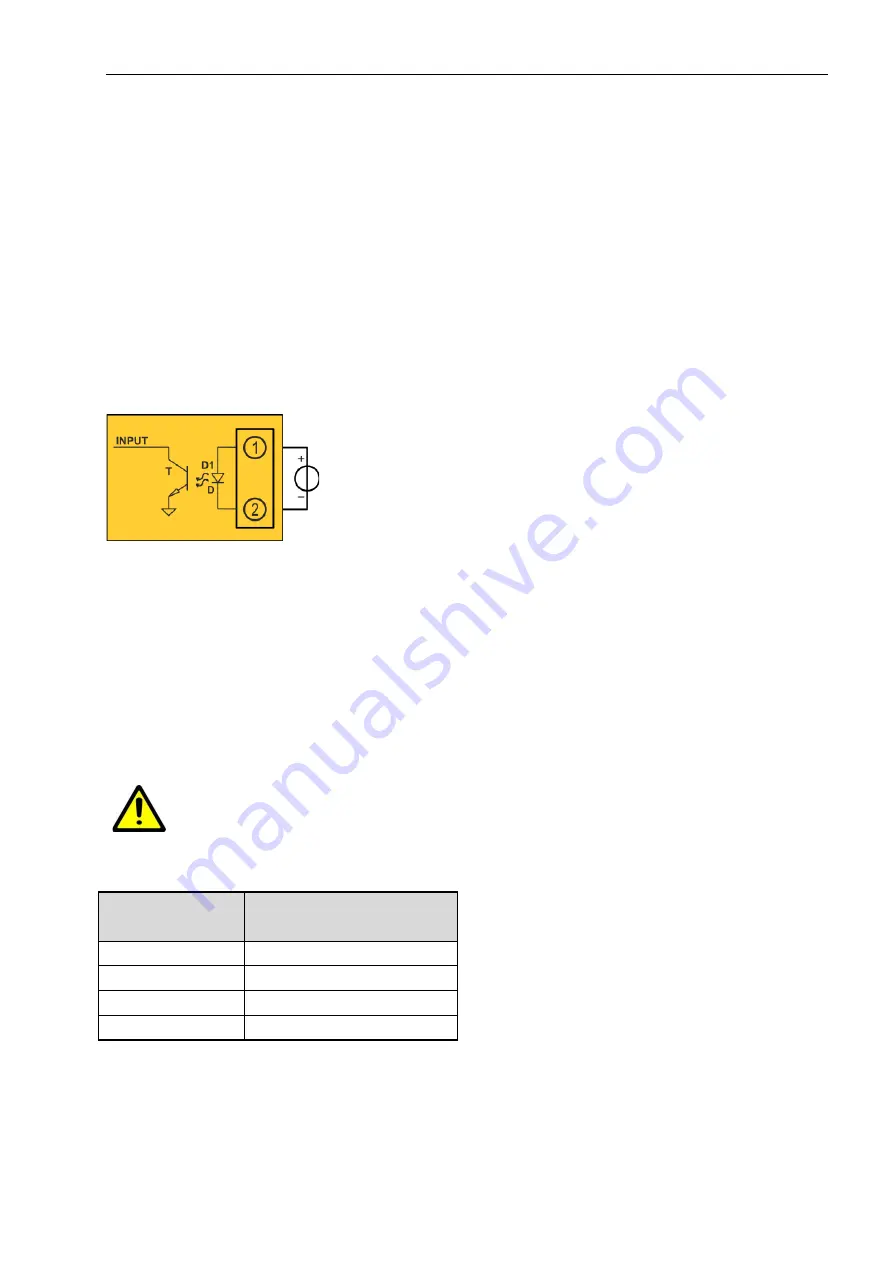
Fig. 2 illustrates how the digital input works. The signal is
applied to the IO terminals 1 and 2. It powers the opto-
coupler, which insulates the input signal and the acquisition
hardware.
All input channels work independently and are potentially isolated. They do not share any
common contacts (e.g. ground line).
Applying a voltage above V
HighMin
between the input terminals 1 (resp. 3, 5, 7) and 2 (resp.
4, 6, 8) powers the LED of the opto-coupler and makes the transistor conductive resulting
in a digital HIGH state level. If the voltage is below V
LowMax
is applied this results in a LOW
state level.
All digital inputs are protected against overvoltage. Applying a voltage higher
than V
InMax
= 30 V or lower than
–
V
InMax
= -30V may damage the input.
Digital Input
Channel
IO Terminals Pins
DI0
1 / 2
DI1
3 / 4
DI2
5 / 6
DI3
7 / 8
Tab. 2 Digital Input Channel IO Terminals
Tab. 2 lists the digital input channels and their corresponding IO terminal pins.
Fig. 2 Isolated Digital Input


