LucidControl DI4DO4, User Manual (1.0)
2022/02/03
Page 8 of 47
2.3.2.2
Digital Output Channels
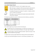
Fig. 3 shows the connection of the first digital output channel.
When the output is activated, the SSR connects terminal 9 with terminal 10,
closing the circuit and switching on the lamp in the shown application.
The polarity of the signal is not relevant. The positive or negative potential
can be connected to any terminal.
SSR outputs are opto-insulated, protecting the hardware behind the SSR
(e.g. the host computer).
The outputs are potential-free and do not share any common contacts e.g. ground line.
Digital Output
Channel
IO Terminals Pins
DO0
9 / 10
DO1
11 / 12
DO2
13 / 14
DO3
15 / 16
Tab. 3 Digital Output Channel IO Terminals
Tab. 3 lists the digital output channels and their IO terminal pins
The SSR outputs are not protected against overcurrent and overvoltage. U
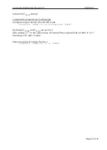
SSRMax
and I
SSRMax
limits must be considered. Otherwise, the output may be damaged.
If inductive loads are controlled, additional protection might be necessary in order
to protect the SSR from high voltage.
The digital output channels support Reflect Mode, Duty-Cycle Mode and On-Off Mode.
For Duty-Cycle and On-Off Modes the minimum on and off times are limited to T
SSRMin
.
Fig. 3 SSR
Output


