Data Logger
6.
OFDISPLAY MODES
There are seven different display modes.
are described below.
6.1
display
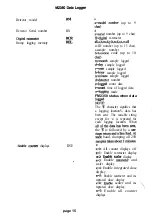
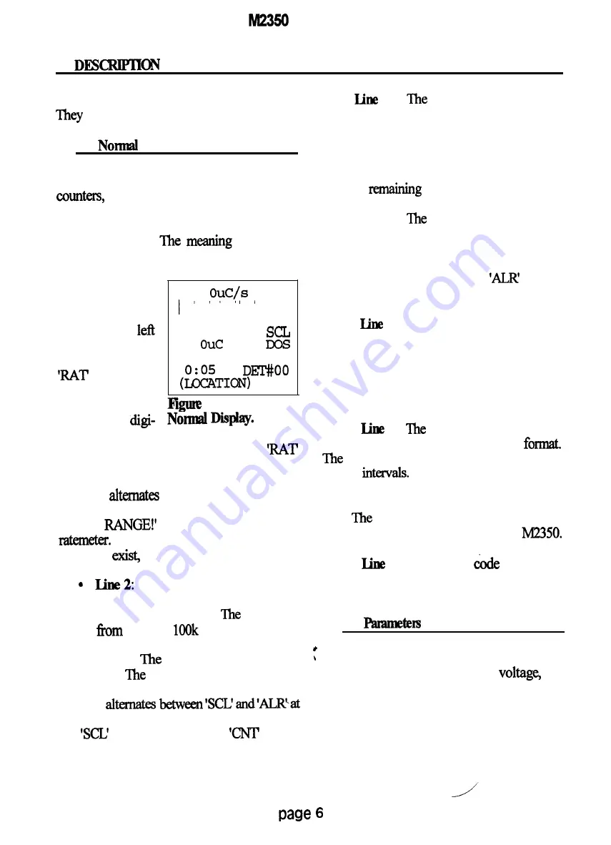
The normal display mode displays all four
the time, the detector number,
thelocation code and the number of samples
stored in the logging memory. The display is
shown in Figure 3.
of each line
follows:
l
Line 1:
T h e d i g i t a l
ratemeter is dis-
played in the
part of the line.
T h e m e s s a g e
indicates
that this is the
digital ratemeter.
0.
RAT
0
s a
10 SEC
0.
4MIN DOS
#000
3.
If there
is a
t a l r a t e m e t e r
alarm, the message alternates between
and ‘AIR at one-second intervals. If there is
a
detector overload, the message ‘OVER
LOAD!’
with the digital ratemeter
reading. If there is an overrange, the message
‘OVER
alternates with the digital
If both overload and overrange
conditions
the overload message is used.
Thefivedecadelogbargraph
is displayed on this line. The count rate is
always in counts per second
bar graph
covers
1 cps to
cps.
l
Line 3:
scaler readout is displayed
on this line.
message ‘SCL’ indicates that
this is the scaler. If there is a scaler alarm, the
message
one-second intervals. Between the scaler and
the
message, the message
appears
when the scaler is counting.
l
4:
scaler count time is
displayed here. The ‘SCL’ message is always
on and indicates that this is the scaler timer.
When the scaler is not counting the time
displayed is the count time for the scaler. If
the scaler is counting, the time displayed is
the time
until the count is done.
l
Line 5:
integrated dose readout is
displayed on this line. The message ‘DOS’
indicates that this is the integrated dose. If
thee is an integrated dose alarm, the message
alternates between ‘DOS’ and
at one
second intervals.
l
6:
The integrated dose count time
is displayed here. ‘The ‘DOS’ message is
always on and indicates that this is the
integrated dose timer. ‘The time displayed is
the elapsed time in minutes since the integrat-
ed dose started accumulating.
l
7:
clock time is displayed at
the left side of this line in the 24 hour
colon blinks on and off at one-half
second
If the battery voltage is 4.4
volts or lower, the message ‘LO BAT
alternates with the time at one second inter-
vals.
right part of the line shows which
detector settings are beiig used by the
l
8: The location
is displayed
in this line. The number of logged readings is
displayed at the right side of this line.
6.2
display
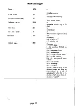
The parameters display mode displays both
ratemeters, the scaler, the high
the
window, the battery voltage, the threshold, the
time, the date and the user identification
number. The display is shown in Figure 4.
The meaning of each line follows:
Summary of Contents for 2350
Page 55: ...page 50 ...
Page 57: ...CPI E w l J h nm ...
Page 58: ...r CR1 14 nra ...
Page 59: ......
Page 60: ......
Page 61: ... I VYIO I I e Ilc ...
Page 62: ......
Page 63: ... a 3 Pa 4 n r n 1 3 4 n a ...
Page 64: ......
Page 65: ......


