background image

The painted bodywork on your Luggie Scooter can be
lightly washed with clean soapy water. Do not use abrasive
cleaners or strong detergents. This could fade the color, an
auto type shampoo works well.

Do not hose down your Luggie with a powerful 

cleaner. Water could be forced into the electronics and 
cause permanent damage.
On the painted finish, be cautious not to wash with a dirty
cloth as this could scratch the paint finish. Auto polish can
be used to keep the paintwork and bright chrome parts in
pristine condition.
The metal framework of your Luggie should be cleaned
once a year and any paintwork damaged should be treated
to prevent further attack from the elements.
Do not store your Luggie in damp conditions. This may affect 
the electronics if left for very long periods of time. Moisture, 
if left unattended can cause deterioration on metal work, 
protect with proprietory cleaners.

Servicing of the drive electronics and charger should only be
carried out by your local Luggie service dealer. These
units are sealed and should not be opened. BROKEN
SEALS WILL INVALIDATE YOUR GUARANTEE.

This unit is factory filled and will not normally need
additional lubrication.
Note: Your Luggie transmission is filled  with a special 
lubricant. Do not attempt to force grease into  the 
transmission as this will contaminate the original lubrication
and will invalidate your guarantee.

Take care when lifting the transmission, keep well 

away from clothing. It is normal to find a light film of 
lubrication around this part.

If the motor brake is functioning correctly and 

the drive is engaged you will not be able to push your machine 
when it is switched off. Or switched on with the speed control 
lever in the 'zero speed', central position.

BODYWORK

ELECTRONICS

DRIVE TRANSMISSION LUBRICATION

MOTOR BRAKES

Motor Brake: 


Remove salt contact as this

is very corrosive to bright metal parts.

Caution :

Do not operate your Luggie in exceptional weather conditions 
ie. very heavy rain. Cover your machine up, if it is to be 
left unattended and outside for a long period of time.

Do not drive through deep water with your Luggie. This 
could damage the electronic speed controller. Sea and road 
salts are very corrosive and should be neutralised quickly.

Caution :

Note: Check the Freewheeling Instructions first.

Safety Note: For your own safety, we recommend that you 
check the function of your Luggie brakes prior to a journey.

BODYWORK

MOTOR BRAKES

Motor Brake:

 Luggie

Caution :

Caution :


Luggie 

Luggie

Luggie 

 Luggie

Luggie


ELECTRONICS

DRIVE TRANSMISSION LUBRICATION


Luggie

Note: Check the Freewheeling Instructions first.

When you drive your Luggie and 

you let go of the speed control lever your Luggie should 
reduce speed very quickly. If you  Notice a change in the 
normal slowing/braking condition, and your Luggie does 
not slow down quickly, please do not use your machine, 
contact your Luggie distributor.

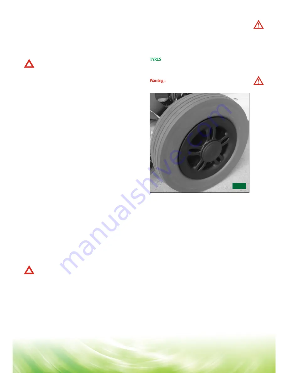
Check the condition of your tyres regularly. Look for signs of 
wear, cuts and foreign objects lodged in the tread ( Fig 20 ).

Your Luggie is designed with 'split' wheel rims.

Do not remove wheel bolts with the wheel inflated.

 Warning :

Driving Brake:


 Warning :

Driving Brake:


Luggie 

Luggie

Luggie

Luggie 

Luggie

21

FIG 20

TYRE SERVICING REAR WHEEL

To remove a rear wheel from your Luggie for the service of a
tyre or tube carry out the following Instructions (only 
competent people should carry out this procedure).

1. Switch off your Luggie.
2. Using a suitable body stand, lift the side of the vehicle
    you wish to service off the ground. Place the stand
    under the chassis. Care must be taken when lifting
    heavy loads, you may need a friend to help you. Care
    should also be taken when working on a stand.
    Please be safe. Do not lift by the plastic bodywork.
3. With the aid of a 13mm spanner(not supplied) remove
    the centre hub nut and washer.


4. Slide the wheel from the mounting axle.


Rear wheels are fitted to the drive axle via a hub which


locates onto a key.These wheels fit tight onto the axle


and may need some pressure from a bearing puller onto


the wheel hub to release them from the axles. Look for


spacing washers and take care not to mislay the drive


key which fits between the wheel hub and the axle shaft.


Tore-assemble the wheel simply follow the above procedure


in reverse order noting the following points:

1. Make certain that you replace any spacing washers and
    keys in the order that they were removed.


TYRE SERVICING REAR WHEEL

Luggie 

Luggie

Please be safe. Do not lift by the plastic bodywork.

Summary of Contents for FR168-4 (IT)

Page 1: ...FR168 4 IT uggi R USERS INSTRUCTION MANUAL Smart Fold Easy Go...

Page 2: ...lined on page 4 5 6 9 10 13 of this owner s manual If you have any queries concerning operation or maintenance consult your authorised Luggie dealer Please keep in mind that the operator of the Scoote...

Page 3: ...e user in a moving vehicle for advice on transporting consult your selling agent Simple to remove battery pack The product should be serviced as recommended by an approved Luggie distributor in order...

Page 4: ...FINITION It is designed for a single occupant who experiences difficulty or discomfort when walking for prolonged periods but has the use of both legs and the physical visual and cognitive ability to...

Page 5: ...to remove the safety valves situated in the top of the battery Failure to observe this warning will invalidate your battery guarantee 24 Do not drive your Luggie through deep water or clean with a hig...

Page 6: ...ll free Please consult your carrier for details The advanced speed controller has been designed with extensive self checking circuits to give you the maximum state of the art safety technology Fully a...

Page 7: ...d firmly into position 3 With the combination of the height adjustment together with the handlebar movement you should find a suitably comfortable driving position Always make certain the handlebar lo...

Page 8: ...your batteries are losing power but you will still have power to spare When the needle falls into the red sector your batteries are low in power and need to be re charged although you will still have...

Page 9: ...n this mode the status light on your console will flash five times If your Luggie Scooter is in the freewheel Luggie FREEWHEEL PROCEDURE Warning Warning uggie Luggie Luggie Luggie s Luggie Luggie Lugg...

Page 10: ...Luggie Luggie BRAKING GENERAL SAFETY CHECK Warning Do not attempt to operate your new Luggie Scooter for the first time without completely reading and understanding all of the facts in this Users Ins...

Page 11: ...ces such as packed soil grass and gravel These surfaces may not be sound and fail to give OUTDOOR DRIVING SURFACES STREET AND ROADWAY DRIVING INSURANCE Warning Warning Luggie Luggie Luggie Luggie Lugg...

Page 12: ...e of the incline Drive your Scooter smoothly up the incline without stopping this greatly reduces the possibility of a tip or fall You should not travel over a potentially hazardous incline i e areas...

Page 13: ...ery Located on middle of chassis SAFETY WARNING INSTRUCTION LABLES 13 Located on front of the Scooter s chassis Located on top of locking of pull lever Located on middle of folding chassis Located at...

Page 14: ...n open area free from traffic and preferably with an attendant who can assist you Next switch on The battery state indicator will move and the status light will illuminate Gently press the right thumb...

Page 15: ...climb All of these factors can affect the rear stability of your Luggie Scooter If you are unsure of your capability to climb an obstacle then try another route always think safety first Please take c...

Page 16: ...surfaces Work out the best position to stow each part of your machine this will vary with different car designs An old blanket can be used to stop the various parts rubbing against each other It is go...

Page 17: ...ntial means that its two batteries must be maintained with full power Nightly recharging after use will help you to give them a longer life and will ensure your Luggie is always ready to go when you a...

Page 18: ...y be short or open If the Charging Indicator ORANGE is still off the battery charger may be defective 3 If the Charging Indicator ORANGE does not turn Green Fully Charged The battery is not charged no...

Page 19: ...re can I re charge my batteries How often must I re charge my batteries How can I ensure maximum battery life 19 5 Batteries carry a limited guarantee from the original manufacturer which is subject t...

Page 20: ...atteries must not be disposed of by means of a domestic refuse disposal unit dustbin etc Please contact your Dealer to dispose of used batteries Please note he may charge for this service The batterie...

Page 21: ...ectronic speed controller Sea and road salts are very corrosive and should be neutralised quickly Caution Note Check the Freewheeling Instructions first Safety Note For your own safety we recommend th...

Page 22: ...eel has two bearings which may have various spacing washers between the fork please note the order of these washers Remove the tyre from the wheel by following point 6 above for Rear Wheels using a 10...

Page 23: ...it will go with the locking lever released ie pushed upwards Support steering column 2 Release the black clamping lever down and test that the tiller is tightly held in place adjust clamp nut until co...

Page 24: ...ped below 23 3 volts in neutral Recharge the batteries soon The battery voltage at Controller has dropped to 16 5 volts Check the battery condition and the connections The battery voltage at the contr...

Page 25: ...er battery Conforms to EN60335 2 29 and EN12184 24 volt DC Rear wheel direct drive via sealed drive axle 24 volt DC Permanent magnet totally enclosed for outdoor use Internal brushes 3 0 Amp no load 7...

Page 26: ...BATTERY WIRING DIAGRAM BATTERY WIRING DIAGRAM SIZE SPECIFICATION Luggie CIRCUIT DIAGRAMS 26 WHITE...

Page 27: ...een tested to the following standards with reference to EN12184 Emissions EN50022 B Immunity IEC1000 4 3 E S D IEC801 2 All figures speeds measurements and capacities shown in this manual are approxim...

Page 28: ...ure will normally become obvious within the first two months of use See batteries and battery charging section of this manual Any gradual deterioration in the performance after this period is normal a...

Page 29: ...also benefit from a documented record and this book should accompany the Scooter when service or repair work is carried out The service agent will complete this section and return the book to you DETA...

Page 30: ...ll also benefit from a documented record and this book should accompany the Scooter when service or repair work is carried out The service agent will complete this section and return the book to you D...

Page 31: ...ice agent will also benefit from a documented record and this book should accompany the Scooter when service or repair work is carried out The service agent will complete this section and return the b...

Page 32: ...o reproduction in any from of this manual in whole or in part except for brief quotations in critical articles or reviews may be made without the written authorisation from Luggie May 1 2009 1000 No 2...

Reviews: