background image

4


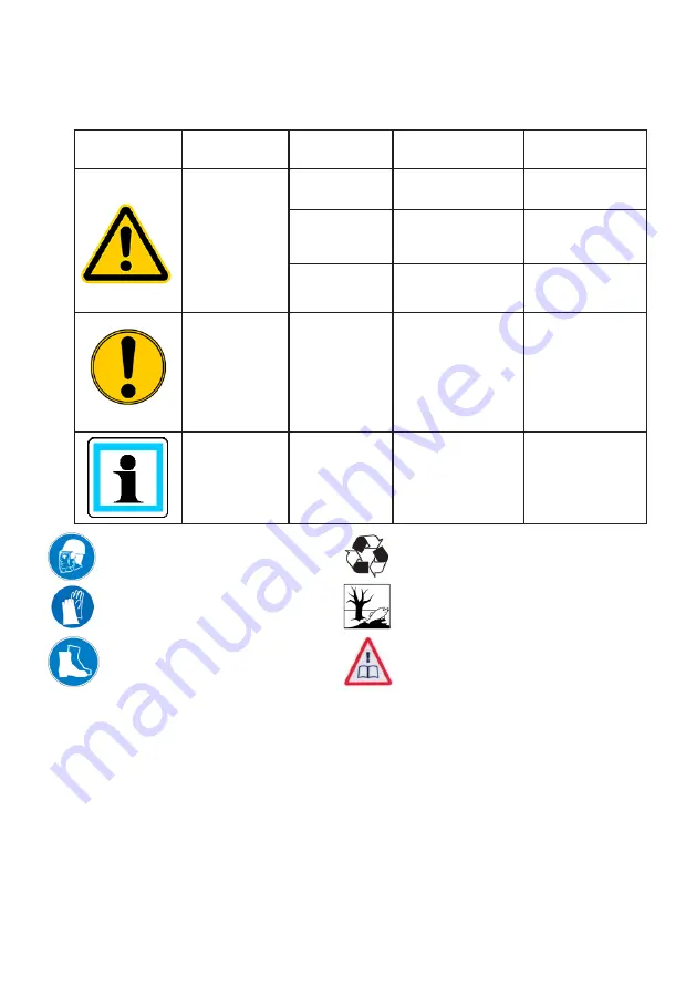
Wear helmet with face guard


Wear protective gloves


Wear safety shoes

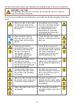
We distinguish between various categories of safety instructions. The table shown below 

shows you the overview, via the assignment of symbols (pictograms) and signal words, of 

the concrete danger and the possible consequences.

1.  Danger classes

Pictogram

Damage / 

injury to

Key word

Definition

Consequences

human

DANGER!

Immediate danger  Death or major 

injury

WARNING!

Potentially 

dangerous 

situation

Potential death or 

major injury

CAUTION!

Less dangerous 

situation

Minor or slight 

injury

device

CAUTION!

Danger of damage 

to device / 

environment

Damage to the 

equipment, 

damage to the 

environment, 

damage to 

surrounding 

materials

-

NOTE

Advice for 

application and 

other important / 

useful information 

and advice

No injury / 

damage to 

persons / 

environment / 

equipment 

2.  Product safety

LUKAS products are developed and produced in order to ensure the best performance and 

quality with proper use.

The safety of the operator is the most important consideration in the product design. 

In addition, the operating instructions are to help in using the LUKAS products safely.

In addition to the operating instructions, all generally applicable, statutory and other 

binding rules for accident prevention and for environmental protection must be heeded and 

disseminated.

The device must only be operated by educated persons who are trained in safety technology, 

since otherwise there is a risk of injury.

We advise all users before using the device to carefully read through the operating instructions 

and to follow the instructions contained therein without exception.


Proper recycling


Protect the environment


Read and follow operating    


 instructions

Summary of Contents for 81-50-35

Page 1: ...179101085 EN Translation of the original instruction manual replaces 02 2013 Edition 07 2017 Instruction manual for rescue equipment Hand pump LH2 Foot pump LF2 and accessories...

Page 2: ...2...

Page 3: ...ioning 13 7 1 Unlocking the pump 13 7 2 Retracting the handle 13 7 3 Bleeding the pump 13 8 Operation 14 8 1 Operation 14 8 2 Shutdown storage 15 9 Transport 15 10 Maintenance and repair 15 10 1 Basic...

Page 4: ...l information and advice No injury damage to persons environment equipment 2 Product safety LUKAS products are developed and produced in order to ensure the best performance and quality with proper us...

Page 5: ...usively with hydraulic devices If this work is unavoidable sufficient mechanical supports are additionally required Check all lines hoses and screwed connections for leaks and externally visible damag...

Page 6: ...an be detrimental to health if they are swallowed or their vapours are inhaled Direct contact with the skin should be avoided for the same reason Also when handling hydraulic fluids note that they can...

Page 7: ...replacement drive source along with the LUKAS hydraulic unit e g in areas at risk for explosion Use with equipment of other manufacturers is possible but requires technical testing and approval of LUK...

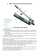
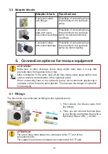
Page 8: ...re see chapter Technical Data A pressure port P with a G1 4 thread and a return port T with an M10 thread are directly available as ports on the pump To connect rescue equipment adapter blocks must be...

Page 9: ...d during the pumping procedure as with the hand lever To avoid possible injuries secure the foot pump lever with your hand before unlocking it Holding the pump lever down will prevent it from jumping...

Page 10: ...ay that prevents them from getting dirty or lost After completion of the work seal off all lines using screw plugs and or dust caps to prevent contamination of the hydraulic pump When connecting lines...

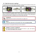
Page 11: ...the locking sleeve Finally turn the locking sleeve into Position Y The connection is then made and secured Decoupling is done in the reverse sequence WARNING CAUTION ATTENTION The quick disconnect cou...

Page 12: ...lso possible assuming the connected equipment is not turned on NOTE We recommend when ambient temperatures are low and extension hoses hose winders are used connecting the coupling halves in a depress...

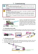
Page 13: ...he usable amount changes The oil fill plug must always be unscrewed one turn before starting the operation of the hydraulic pump This enables the aeration and bleeding of the hydraulic tank After the...

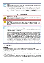
Page 14: ...the discharge valve is opened too quickly turning counter clockwise i e the check valve incorporated in the male quick disconnect coupling blocks the return flow of oil while the connection between p...

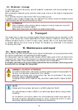
Page 15: ...only be performed by the device manufacturer or by personnel trained by the device manufacturer and authorised LUKAS dealers All components must be replaced with original LUKAS spare parts which are...

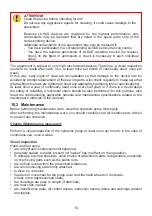
Page 16: ...e equipment may only be replaced if You have participated in a corresponding LUKAS service training course You have the express permission of LUKAS customer service by request check on the grant of pe...

Page 17: ...t once every half year ATTENTION Add hydraulic fluid only if the hydraulic pump is disconnected from the lines or the equipment operated with the pump is hydraulically depressurised Otherwise after fi...

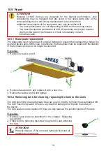
Page 18: ...device upon further use In particular the base plate must be replaced if the stability of the hydraulic pump can no longer be ensured Procedure 1 Remove screws A and B 2 Remove base plate C and replac...

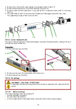
Page 19: ...replacement The lever must be replaced if external damage is present that represents a danger for user and device upon further use Procedure 1 Drive out dowel pin item M M N 2 Remove lever item N and...

Page 20: ...n new screw on male coupling and tighten with a torque of MA 35 Nm ATTENTION The return port must always be equipped with a female quick disconnect coupling The supply port should instead be equipped...

Page 21: ...as described in the chapter Bleeding the pump Defect on the device Heed the specifications of the separate operating instructions of the device Connected device moves but does not hold pressure or do...

Page 22: ...aulic tank too low Add hydraulic fluid up to max fill level Attention move the device back into the base position before adding fluid Usable hydraulic fluid quantity of the pump is insufficient Use a...

Page 23: ...age at the couplings Coupling defective Coupling should be replaced immediately In the case of a quick disconnect coupling system Leakage on the male coupling Safety valve has responded in the decoupl...

Page 24: ...lic fluid tank LH 2 1 8 50 Tank size max operating pressure in MPa 1 MPa 10 bar 12 1 1 Pump labelling Model series NOTE The automatic pressure switch from low pressure to high pressure occurs at 2 MPa...

Page 25: ...F HM 10 VG 10 recommended viscosity range 10 200 mm s 10 200 cSt Supplied with HM 10 DIN ISO 6743 4 ATTENTION Before using hydraulic fluids that do not correspond to the aforementioned specifications...

Page 26: ...e Safety factor Burst pressure max Operating pressure min 4 1 Temperature resistance 40 C 100 C 40 F 212 F Operating fluid Mineral oil according to DIN EN ISO 6743 4 Operating temperature C F 20 55 4...

Page 27: ...27 13 Notes...
Page 28: ...ct to change LUKAS Hydraulik GmbH A Unit of IDEX Corporation Weinstra e 39 D 91058 Erlangen Tel 0049 0 91 31 698 0 Fax 0049 0 91 31 698 394 e mail lukas info idexcorp com www lukas com Made in GERMANY...

Reviews: