background image

12

  4.3  Operation of traction devices KSV11, KSV13, KSV13/100, 

KSV8/50, KSV8/258

1.  Attach the traction device as described under point 4.2.

2.  Completely open the rescue device.

3.  Loop  the  traction  chains  around  the  pulling  point  or  fastening  point,  and  push  the 

shortening hooks over a chain link. While doing so, make sure that the traction chain is 

as taut as possible on the object and cannot slip.

4.  Hook the chain into the shortening hook of the connector. Pull the traction chain as tight 

as possible.

5.  Before the actual traction process, check the chains once more for a secure hold.

6.  To pull, close the spreader or the combi tool. When pulling, always make sure that the 

traction chain is not deflected by obstacles.

7.  If the pulling distance is insufficient, it must first be secured with tension chains or other 

means. Only then open the spreader and proceed according to points 4 and 5.

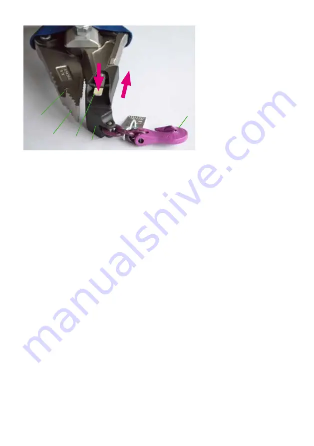
Attaching the traction device to the LUKAS spreader or combi tool

1.  Completely open the arms of the spreader or of the combi tool.

2.  Completely press down the release button (5) on the connector (3) (direction A).

3.  Keep the release button (5) held down and push the connector (3) over the tip (1) of the 

combi arm as shown in the picture (direction B).

4.  Let go of the release button (5) and make sure that the locking bolt of the connector (4) 

engages into the attachment hole (2) of the combi tool arm.

5.  Make sure that the connector (4) is correctly engaged by pulling it by hand.

6.  To remove the connector (4) press the release button (5) down again and pull off the 

connector.

1   Arm tip of the combi tool

2  Attachment hole for the 

traction device

3  Connector

5  Release button of the 

connector

6  Shortening hook of the 

connector

5

1

6

B

A

3

2

Summary of Contents for 81-67-20

Page 1: ...Traction device operating instructions 84150913085 EN Chain sets Original operating instructions replaces 01 2020 Edition 11 2020 KSV11 KSV13 KSV13 100 KSV8 50 KSV8 258 KSS20 ...

Page 2: ...and attachment of KSV8 50 and KSV8 258 11 4 3 Operation of traction devices KSV11 KSV13 KSV13 100 KSV8 50 KSV8 258 12 4 4 Design attachment and operation of KSS20 13 5 Maintenance and service 15 5 1 Visual inspection of traction devices 15 6 Traction device usage instructions 17 7 Individual components from traction devices for replacement requirements 19 8 Notes 19 ...

Page 3: ...ific danger and the possible consequences 1 Danger classifications Pictogram Damage injury to Keyword Definition Consequences Persons DANGER Immediate danger Death or severe injury WARNING Potentially dangerous situation Potential death or serious injury CAUTION Less dangerous situation Minor or slight injury Property ATTENTION Risk of damage to property environment Damage to the device damage to ...

Page 4: ...he directions contained therein without restriction We further recommend that you have a qualified trainer show you how to use the product WARNING CAUTION The operating instructions for accessories must also be taken into account Even if you have already received instructions on how to use the equipment you should still read through the following safety instructions again WARNING CAUTION Please en...

Page 5: ...he traction device and in the operating instructions All safety and danger information on the traction device must be complete and in a legible condition Safety devices must never be disabled Only genuine LUKAS accessories and spare parts are to be used for repairs Before using the traction device make sure that nobody is endangered Observe all intervals for recurring tests and or inspections that...

Page 6: ...nd other binding national and international accident prevention regulations must be observed and operators must be instructed accordingly WARNING CAUTION ATTENTION This device is intended exclusively for the purpose described in the instruction manual see chapter Proper use Any other use is not in accordance with its proper use The manufacturer supplier is not liable for any damage resulting from ...

Page 7: ...hains under load over sharp edges Chains lying on the ground must not be rolled over by a load WARNING CAUTION ATTENTION When traction devices are used in potentially explosive atmospheres make sure that an explosion cannot be triggered by the traction device working with the traction device cannot cause an explosion e g sparks can be produced The responsibility for the prevention of explosions or...

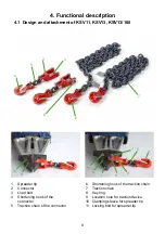
Page 8: ...1 KSV13 KSV13 100 1 Spreader tip 2 Connector 3 Load bolt 4 Shortening hook of the connector 5 Traction chain of the connector 6 Shortening hook of the traction chain 7 Traction chain 8 Key ring 9 Location hole for traction device 10 Clamping sleeve for spreader tip 11 Locking bolt for spreader tip ...

Page 9: ...ip is attached to the rescue equipment arm with a clamping sleeve 10 Under no circumstances may the traction devices be fixed in the hole of the clamping sleeve Failure to observe this can lead to overloading the traction device or the spreader Attaching the traction device to the LUKAS SC 358 SC 757 E2 and SC 758 To be able to attach the traction device to the SC 358 SC 757 E2 and SC 758 the spre...

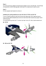
Page 10: ...rwards to remove it Attaching the pulling attachment to the SC 358 SC 757 E2 and SC 758 To do so start by pulling out the bolt of the traction attachment until it reaches the end stop push the traction attachment onto the arm and insert the bolt all the way again until it clicks into place The corresponding chain lock C can then be fixed in hole B of the traction attachment SC 757 E2 SC 358 and SC...

Page 11: ...f the traction chain Attaching the traction device to the traction attachment of the combi tool 1 Completely open the arms of the combi tool 2 Pull out the load bolt 3 on the key ring 8 up to the stop 3 Push the connector 2 over the traction attachment 4 Completely insert the load bolt 3 into the location hole provided for the purpose in the traction attachment until it engages ...

Page 12: ...ent it must first be secured with tension chains or other means Only then open the spreader and proceed according to points 4 and 5 Attaching the traction device to the LUKAS spreader or combi tool 1 Completely open the arms of the spreader or of the combi tool 2 Completely press down the release button 5 on the connector 3 direction A 3 Keep the release button 5 held down and push the connector 3...

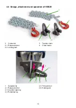
Page 13: ... 1 2 1 Spreader tip 2 1 Release button 2 3 Insertion opening 2 4 Retaining lug 2 5 Through duct 2 6 Holding slot 4 4 Design attachment and operation of KSS20 3 2 Connector 2 1 Release button 2 2 Locking bolt 3 Traction chain 4 Chain hooks ...

Page 14: ...und the traction point by hooking in the hook 2 Pull the end of the chain through the connector To do so first pull direction C the end of the chain by hand through the insertion opening 2 3 Keep the chain as taut as possible while doing so 3 Push a chain link through the duct 2 5 around the retaining lug 2 4 into the holding slot 2 6 direction D Unintentional loosening of the chain is prevented b...

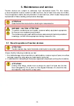
Page 15: ...ition ATTENTION Traction devices may never be tested under load or even when overloaded Traction devices are subject to extremely high mechanical loads For this reason a visual inspection must be carried out after each use but at least once every six months These inspections enable the early detection of wear and tear which means that punctual replacement of these wearing parts prevents breakage A...

Page 16: ...rovided that they correspond to the manufacturer s condition on delivery are present and in perfect condition 5 It must be possible to move accessory shoes shackles and locking pins with minimal effort Chain set Target diameter mm target length of chain link mm KSV8 50 8 24 KSV8 258 KSV11 10 30 KSS20 KSV13 13 39 KSV13 100 ...

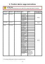
Page 17: ...0 E2 62 kN SP 300 SP 310 E2 SP 310 SP 333 eWXT SP 333 E2 SP 333 SP 555 eWXT SP 555 E2 SP 555 SP 777 eWXT SP 777 E2 SP 777 SP 510 LSP 60 EN LSP 40 EN SC 358 eWXT only in conjunction with traction attachment 81 67 21 SC 358 E2 SC 358 The actual load depends on the rescue equipment used 6 Traction device usage instructions ATTENTION The traction devices may only be used for the equipment listed in th...

Page 18: ...P300 only permitted with multi function tip SP310 only permitted with multi function tip LSP40EN LSP40B LSP100 KSV13 81 67 30 12mm SC757E2 only in conjunction with traction attachment 393R029 98 kN SC 758 eWXT only in conjunction with traction attachment 81 67 32 SC 758 E2 SC 758 SC557 LSP100 KSV13 100 81 67 31 16mm SP512 98 kN SP80EN The actual load depends on the rescue equipment used ...

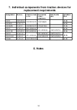
Page 19: ... 50 kN KSV8 258 81 67 11 V84150912217 173023150S 35 kN KSV11 81 67 20 HR149330018 HR149330044 V84150912703 62 kN KSV11 80 841509131 HR149330043 80 kN KSV13 81 67 30 HR149330030 HR149330035 V84150912703 98 kN KSV13 100 81 67 31 V84150912910 V84150912902 KSS20 81 67 40 V84150912610 64 kN 7 Individual components from traction devices for replacement requirements 8 Notes ...

Page 20: ...langen Germany Tel 0049 0 91 31 698 0 Fax 0049 0 91 31 698 394 email lukas info idexcorp com www lukas com Made in GERMANY Copyright 2020 LUKAS Hydraulik GmbH Zugvorrichtungen_84150913085_EN indd Subject to change Please duly dispose of all packaging materials and removed items ...

Reviews: