17.10.2008
Page 15
• AMIN 12-125T WH •
6
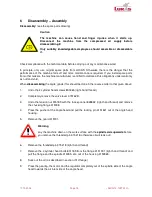
Disassembly – Assembly
Disassembly:
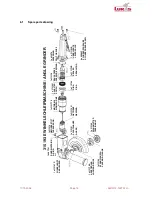
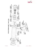
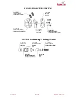
(see the spare parts drawing)
Caution
The machine can cause hand and finger injuries when it starts up.
Disconnect the machine from the compressed air supply before
disassembling it!
Only suitably knowledgeable employees should assemble or disassemble
it.
Check compliance with the technical data before carrying out any maintenance work!
In principle, only use original spare parts from LUKAS. Otherwise there is the danger that the
performance of the machine falls off and more maintenance is required. If you install spare parts
from other makers, the machine manufacturer is entitled to declare all his obligations under warranty
as null and void.
When
disassembling
the angle grinder this should be done in the reverse order to that given above:
1.
Undo the 4 cylinder head screws 800465 (right-hand thread).
2.
Completely remove the valve lever 315162 B.
3.
Undo the tension nut 315189 with the face spanner 828832 (right-hand thread) and remove
the chucking flange 315188.
4.
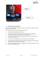
Press the pusher at the angle head and pull the locking pin 3151821 out of the angle head
housing.
5.
Remove the guard 315191.
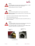
Warning
Lay the machine down on the work surface with the
spindle side upwards
before
you remove the threaded pin 315218, otherwise oil will leak out!
6.
Remove the threaded pin 315218 (right-hand thread).
7.
Remove the 4 cylinder head bolts 801189 from the flange 3151901 (right-hand thread) and
pull the flange and the spindle 315095, etc. out of the housing 3150965.
8.
Suck out the oil (as described in section
Oil Change
).
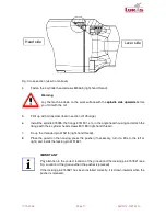
9.
Press the gearing, the motor and the regulator completely out of the spindle side of the angle
head towards the air inlet side of the angle head.

