17.10.2008
Page 17
• AMIN 12-125T WH •
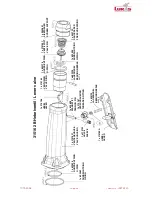
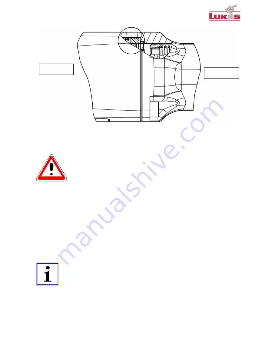
Fig.: Cross-section (view from above)
4.
Fasten the 4 cylinder head screws 800465 (right-hand thread).
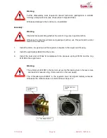
Warning
Lay the machine down on the work surface with the
spindle side upwards
before
you fill it with the oil!
5.
Fill it up with oil (as described in section
Oil Change
).
6.
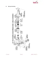
Install the spindle 315095, the flange 3151901, etc. in the angle head housing and attach the
flange with the 4 cylinder head screws 801189 (right-hand thread).
7.
Do up the threaded pin 315218 (right-hand thread).
8.
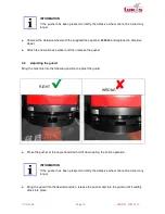
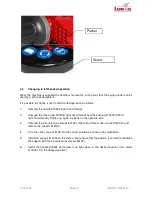
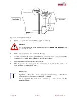
Place the guard on the housing, press the pusher (if necessary, turn it a little to the left or
right) and install the locking pin 3151821.
IMPORTANT
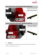
Pay attention to the correct location of the groove and the locking pin 3151821 (see
Fig.
Location of the groove when the pusher is pressed
).
If the locking pin 3151821 has been installed correctly, it is drawn inwards when the
pusher is released.
Head side
Lever side


