background image


17.10.2008 

Page 32 

• AMIN 12-125T WH • 

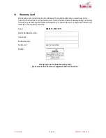
14  Warranty Card 

We hereby grant a warranty in accordance with our written statement of warranty in the 
operation instructions for a period of 6 (six) months from the date of delivery/sale given below 
to cover any defects that are demonstrably due to material, design or construction errors and 
defects for the following machine: 

Type: 

AMIN 12-125T WH 

Serial No./Machine No.: 


Year built: 


Date delivered: 


Date sold: 

see invoice date 

Stamp: 


If making a claim under warranty then 


please send this card to us together with the machine. 


Summary of Contents for AMIN 12-125 TWH

Page 1: ...17 10 2008 Page 1 AMIN 12 125T WH OPERATION INSTRUCTIONS AMIN 12 125 TWH...

Page 2: ...environmental protection regulations 9 2 Intended Use 9 3 Installation 9 4 Starting Up 10 4 1 Changing the abrasive wheel 11 4 2 Adjusting the guard 12 4 3 Changing to left handed operation 13 5 Handl...

Page 3: ...evention the setting up of electrical and mechanical systems and radio interference suppression are to be followed Pay attention to the cleanliness of the workplace in all maintenance and repair work...

Page 4: ...it is possible for dust and vapours to be produced that could create a potentially explosive atmosphere The work pieces must be fixed adequately before starting work Never use the machine in the vicin...

Page 5: ...nsure that it is undamaged and suitable for the intended task Only users with the relevant technical knowledge who have been trained by authorised technicians who are aware of their responsibility may...

Page 6: ...e wheel due to the application of force or impacts or heating up 1 3 Obligations of the owner operator The owner operator is required to ensure that the people who work with the machine are familiar w...

Page 7: ...d maintenance of the machine Operation of the machine with defective safety devices or incorrectly applied or non functional safety and protective devices Failure to comply with the information given...

Page 8: ...a danger that your hands could be crushed drawn in or otherwise injured ESD protected area The component can be destroyed by an electrostatic discharge Only have maintenance and repair work done on h...

Page 9: ...rements for avoiding waste and proper recycling disposal in all work on the machine Especially when carrying out installation maintenance and repair work substances that are a hazard to water such as...

Page 10: ...or A higher flow pressure leads to increased wear If the pressure is too low the performance is reduced Regarding the quality of the compressed air as per ISO 8573 1 we recommend CLASS RESIDUALOIL RES...

Page 11: ...large if such have not been provided by the manufacturer If reducers are used ensure that the chucking flange clamps properly 4 1 Changing the abrasive wheel Bring the machine into the following posit...

Page 12: ...ew abrasive wheel and then release the pusher 4 2 Adjusting the guard Bring the machine into the following position to adjust the guard RIGHT WRONG Press the pusher at the angle head and hold it down...

Page 13: ...the bushing 310000 SW 13 right hand thread Tighten up again the parts on the opposite side 3 Unscrew the 2 countersunk screws 801221 right hand thread Allen socket SW 2 5 and remove the support 31519...

Page 14: ...for right handed operation Location of the slide vane for LEFT HANDED OPERATION Location of the support for left handed operation 5 Handling Only use the machine with due regard to the safety instruc...

Page 15: ...uld be done in the reverse order to that given above 1 Undo the 4 cylinder head screws 800465 right hand thread 2 Completely remove the valve lever 315162 B 3 Undo the tension nut 315189 with the face...

Page 16: ...the machine 1 Install the motor the gearing and the regulator complete in the angle head housing 2 Install the split washer 832070 at the motor 3 Install the lever valve 315162 B complete with the pre...

Page 17: ...angle head housing and attach the flange with the 4 cylinder head screws 801189 right hand thread 7 Do up the threaded pin 315218 right hand thread 8 Place the guard on the housing press the pusher if...

Page 18: ...ng device 315179 A 9 Tighten up the chucking flange 315188 and the tension nut 315189 with the face spanner 828832 right hand thread Make a test run see section Safety instructions for grinders and ch...

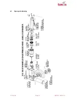
Page 19: ...MOTOR MX AIR MOTOR MX 1 x 3151421 SCHALTER SWITCH 1x315150 DRUCKFEDER PRESSURE SPRING 1 x 832070 FEDERRING SPLIT WASHER 1 x 315162 B HEBELVENTIL LEVER VALVE 4x 800465 ZYLINDERSCHRAUBE CYLINDER HEAD SC...

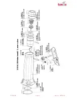
Page 20: ...R GKUGELLAGER ANGULAR ROTARY JOINT 2x 823274 ZYLINDERROLLE CYLINDER ROLL 1 x 315095 SPINDEL SPINDLE 2x 823220 D1CHTRING SEAL RING 1 x 824792 RUNDDICHTRING O RING 32 7x1 3 Viton 1 x 3151901 FLANSCH FLA...

Page 21: ...R PRESSURE SPRING 5x 802185 KUGEL BALL 2x 823825 SPANNSTIFT TENSION PIN 1x 829721 RILLENKUGELLAGER GROOVE BALL BEARING 1 x 3151084 ROTORRITZEL ROTOR PINION 315177 E MOTOR AIR MOTOR 2 x 831035 DICHTRIN...

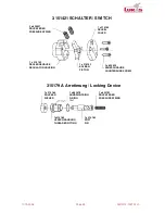
Page 22: ...O R1NG 1 x 3151651 VENTILSTIFT VALVE PIN 1 x 4440801 SIEBTR GER SCREEN SUPPORT 1 x 822626 RUNDDICHTRING O RING 1 x 802583 RUNDDICHTRING O RING 1 x 3151631 VENTILGEH USE VALVE HOUSING 1 x 315102 HULSE...

Page 23: ...1 x 3151295 KOLBEN PISTON 1 x 802182 KUGEL BALL 1 x 826584 DRUCKFEDER PRESSURE SPRING 1 x 802430 RUNDDICHTRING O RING 1 x 802462 RUNDDICHTRING O RING 28 x 1 1 x 824674 DRUCKFEDER PRESSURE SPRING 1 x...

Page 24: ...17 10 2008 Page 24 AMIN 12 125T WH...

Page 25: ...evice 2 x 830027 DRUCKFEDER PRESSURE SPRING 1 x 315142 REGLERGEH USE REGULATOR HOUSING 1 x 315184 DRUCKER PUSHER 1 x 315183 STIFT PIN 1x315185 VERSCHRAUBUNG THREADED FITTING 1 x 832192 DRUCKFEDER PRES...

Page 26: ...on Check the machine regularly for any external damage The oil must be changed after 250 hours of operation Total amount of oil 12 ml Note the information in section Oil Change The total amount of oil...

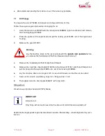
Page 27: ...efore you remove the threaded pin 315218 otherwise oil will leak out 4 Remove the threaded pin 315218 right hand thread 5 Remove the 4 cylinder head bolts 801189 from the flange 3151901 right hand thr...

Page 28: ...lve Automatic overspeed protection was triggered Send the machine back to LUKAS If necessary send the machine to us How to check if the overspeed protection had been triggered 1 Disassemble the machin...

Page 29: ...peed being considerably exceeded and hence could cause severe accidents 9 Scope of Supply Check the scope of supply for completeness QUANTITY DESIGNATION ORDER NO 1 Operation instructions 1 Angle grin...

Page 30: ...n 12 200 Rating kW 2 2 Air consumption under load m3 min 1 8 Air consumption no load m3 min 0 7 Hose diameter mm 13 Roughing discs outer mm 125 Roughing discs inner mm 22 2 Roughing discs width mm 3 4...

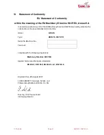
Page 31: ...we hereby state that the construction of the pneumatically driven machine maker LUKAS Type AMIN 12 125T WH Serial No Machine No Year built complies with the following stipulations Machinery Directive...

Page 32: ...6 six months from the date of delivery sale given below to cover any defects that are demonstrably due to material design or construction errors and defects for the following machine Type AMIN 12 125...

Reviews: