17
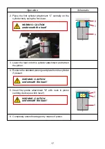
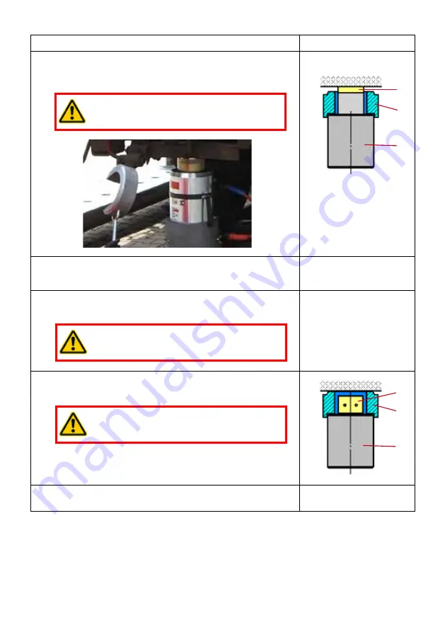
2. Place the first cylinder attachment “C” centrally on the
cylinder body using the fork lever.
Operation
Schematic
WARNING / CAUTION
underneath the load!
B
A
C
3. Lower the load onto this cylinder attachment and retract
the piston.
4. Remove the standard piston guard plate from the cylinder
if present.
5. Insert first piston attachment "D" with neck in piston
centring device (use fork lever!).
WARNING / CAUTION
underneath the load!
WARNING / CAUTION
underneath the load!
D
A
C
6. Completely extend load again by means of piston.
Summary of Contents for HP 25/ T700R
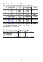
Page 2: ...2...


