background image

5

2. Product safety

LUKAS products are developed and manufactured to guarantee the best performance and 

quality when used properly.

The safety of the operator is the most important consideration in product design. Moreover, 

the operating instructions are intended to aid the safe use of LUKAS products.

The generally applicable, legal and other binding regulations pertaining to the prevention of 

accidents and protection of the environment apply and are to be implemented in addition to 

the operating instructions.

The equipment may only be operated by persons with appropriate training in the safety 

aspects of such equipment – otherwise, there is a danger of injury.

We would like to point out to all users that they should carefully read and adhere to the 

operating instructions in full before they use the equipment.

We further recommend that a qualified trainer train you in the use of the product.

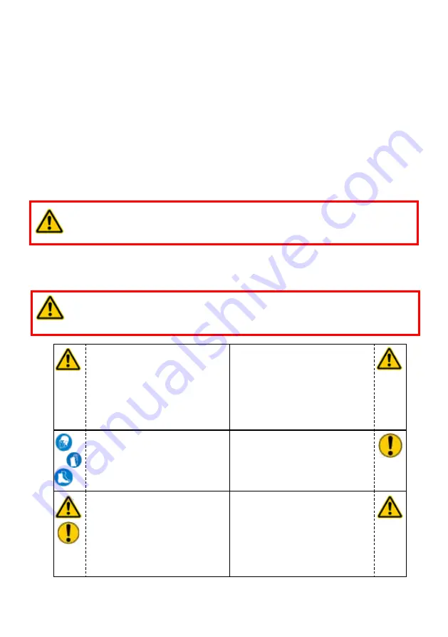
WARNING / TAKE CARE!

The operating instructions for the hoses, the accessories and the connected 

hydraulic equipment must also be observed!

Even if you have already received instructions on how to use the equipment, you should still 

read the following safety notes again.

Please ensure that no body 

parts or clothing are caught 

between the visibly moving 

parts (e.g. piston guard plate 

and cylinder).

Working under loads is 

prohibited if they are raised 

exclusively with hydraulic 

devices. If this work is 

unavoidable, adequate 

mechanical supports are 

additionally required.

Wear protective clothing, 

a safety helmet with visor, 

protective footwear and 

gloves

Inspect the device before and 

after use for visible defects or 

damage

The responsible department 

must be informed immediately 

of any changes (including to 

the operating behaviour)! If 

necessary, the device must 

be deactivated immediately 

and secured!

Inspect all cables, hoses 

and screwed connections 

for leaks and externally 

visible damage! If necessary, 

repair immediately! Squirting 

hydraulic fluid can result in 

injuries and fires.

WARNING / TAKE CARE!

Ensure that the accessories used and the connected equipment are suitable 

for the maximum operating pressure!

Summary of Contents for HP 25/ T700R

Page 1: ...Operating Instructions Re railing Technology 84072376585 GB HP Cylinders Translation of the original operating instructions Edition 12 2011...

Page 2: ...2...

Page 3: ...2 Commissioning 14 7 3 Hydraulic cylinder control 15 8 Use of accessories 16 8 1 Base plate 16 8 2 Multistage sets 16 9 Dismantling the device deactivation following operation 20 9 1 Hydraulic cylinde...

Page 4: ...and the possible consequences 1 Hazard classes Pictogram Damage injury to Key word Definition Consequences human DANGER Immediate danger Death or major injury WARNING Potentially dangerous situation...

Page 5: ...hoses the accessories and the connected hydraulic equipment must also be observed Even if you have already received instructions on how to use the equipment you should still read the following safety...

Page 6: ...ating instructions All safety and danger notices on the device must be kept complete and in a legible condition Any mode of operation which impairs safety and or stability of the device is forbidden C...

Page 7: ...facturer supplier is not liable for any damages resulting from improper use The user bears sole responsibility for such Observance of the operating instructions and compliance with the inspection and...

Page 8: ...vehicle in order to push a towing device underneath it for example HP cylinders in telescopic design offer long hoisting paths with a low retracted overall height The accessories necessary for the pa...

Page 9: ...onal cases Securing against unwanted lowering of the cylinders in the event of a hose breakage is achieved by means of quick stop couplings fitted to the hose If there is any doubt as to which couplin...

Page 10: ...of LUKAS Ensure in particular that the maximum permissible operating pressure for the connected LUKAS equipment is not exceeded NOTE Before you use pumps from a different manufacturer you must contact...

Page 11: ...der Hoses can be connected only when depressurised For dust protection the supplied dust protection caps must be refitted 6 2 Coupling quick disconnect couplings The equipment is connected to the hydr...

Page 12: ...TENTION Hydraulic fluids may produce a lubricating film on the ground CAUTION ATTENTION When using wooden underplates care must be taken that particularly hard wood without damage is used so that the...

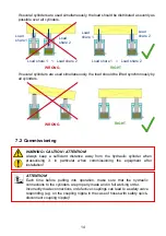
Page 13: ...g staff or the cylinder itself The load should always contact the middle of the piston area Side loads should be avoided WRONG RIGHT Load Load WRONG RIGHT Load Load It is usually not possible to make...

Page 14: ...all cylinders WRONG RIGHT WARNING CAUTION ATTENTION Always keep a sufficient distance away from the hydraulic cylinder when pressurising it in particular when commissioning the equipment after instal...

Page 15: ...inder piston cannot be directly controlled by the cylinder Extending and retracting the cylinder must be controlled via a separate control unit or the connected hydraulic unit 7 2 1 Initial operation...

Page 16: ...cylinders To find out which multistage set is suitable for your cylinder please contact your authorised dealer or LUKAS directly 8 Use of accessories 8 1 Base plate Base plates are provided to Increas...

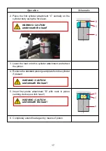
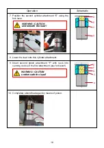
Page 17: ...C 3 Lower the load onto this cylinder attachment and retract the piston 4 Remove the standard piston guard plate from the cylinder if present 5 Insert first piston attachment D with neck in piston cen...

Page 18: ...his cylinder attachment WARNING CAUTION underneath the load Operation Schematic E A C D 9 Insert second piston attachment F with neck into centring device of the first attachment use fork lever 10 Com...

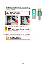
Page 19: ...and piston attachments have been mounted WARNING CAUTION underneath the load WARNING CAUTION ATTENTION Never use several multistage sets at the same time on one HP cylinder as otherwise stability cann...

Page 20: ...nical strain on the device NOTE When hydraulic cylinders are in storage fluctuations in ambient temperature can cause the pistons to move slightly This phenomenon is due to the difference in the expan...

Page 21: ...ry out maintenance and repair work tools appropriate for the job and personal protective equipment are essential Inspections to be carried out Visual inspection Cylinder and piston rod undamaged and n...

Page 22: ...those components in the replacement parts lists for the relevant unit may be replaced Other components on the cylinders may only be exchanged if You have taken part in appropriate LUKAS service traini...

Page 23: ...ent temperatures change substantially When selecting a suitable hydraulic fluid please refer to chapter Hydraulic fluid recommendations Procedure 1 Completely retract the cylinder 2 Dismantle the valv...

Page 24: ...ing replacement parts list for the cylinder Procedure 1 Remove the coupling 2 Position the new coupling and tighten it to the torque stated in the corresponding replacement parts list for the cylinder...

Page 25: ...apply the specified force Hydraulic fluid level in the supplying pump Insufficient hydraulic fluid in the pump Top up hydraulic fluid deaerate Check operating pressure of driving hydraulic unit Press...

Page 26: ...the part to be lifted thereby suddenly increasing the load Secure the load and move using other tools Apply the cylinder at a different point where the load to be moved is lighter Use supporting equip...

Page 27: ...013 Erlangen Phone 49 09131 698 348 Fax 49 09131 698 353 13 Technical Data NOTE The following tables contain only the most important Technical Data Further information about your device is available d...

Page 28: ...6 133 146 133 Compression force piston 3 kN 650 lbf 146 133 max stroke piston 1 mm 90 90 223 in 3 54 3 54 8 78 max stroke piston 2 mm 95 95 228 in 3 74 3 74 8 98 max stroke piston 3 mm 94 in 3 70 Tota...

Page 29: ...39 658 374 326 374 326 max stroke piston 1 mm 89 195 198 253 in 3 50 7 68 7 80 9 96 max stroke piston 2 mm 96 205 200 250 in 3 78 8 07 7 87 9 84 Total piston stroke mm 185 400 398 503 in 7 28 15 75 15...

Page 30: ...15 Bio oil Oil temperature range Oil code Viscosity rating Remarks A 11 2 86 F HL 5 VG 5 B 0 4 122 F HM 10 VG 10 C 17 6 167 F HM 22 VG 22 D 41 0 176 F HM 32 VG 32 E 17 6 158 F HF E15 VG 15 Bio oil rec...

Page 31: ...31 14 EC Declaration of Conformity...

Page 32: ...Phone 49 0 91 31 698 0 Fax 49 0 91 31 698 394 e mail lukas info idexcorp com www lukas com Made in GERMANY Copyright 2011 LUKAS Hydraulik GmbH HP_Zylinder_BA_GB_84072376585_1211 indd Subject to revisi...

Reviews: