background image

9

7.3 Hydraulic power package

A LUKAS motor pump of PO6... LSI series is to be used for operating the devices. If the
power pack comes from a manufacturer other than LUKAS, it must be ensured that it
fulfills the LUKAS specifications (see connection diagram), as otherwise dangers may
occur for which LUKAS cannot be held liable. Especially it has to be made sure that the
permissible working pressure of 50 MPa (500 bar) is without consultation with LUKAS
not exceeded.

7.4 Hoses

The connection between pump power pack and cutter unit is normally effected with
LUKAS hoses. If pipes are to be used, please contact LUKAS.

7.5 Control of movements in operation

7.5.1 LSI 600 

(device without valve for externally controlled operation)

For hydraulic connection two extra hoses are required (hoses to be ordered separately).
The hoses are to be mounted to the pressure ports in the cylinder bottom and to be
tightened with a torque of 45 Nm. When fitting the cutter unit to a manipulator, certain
principles must be absolutely observed to avoid any risk for persons and the device:

- The device must be fitted swivelling around its longitudinal axis (made possible by

means of an axis of rotation on the robot or an adequate rotor sleeve / LUKAS special
accessories) so that before the cutting operation it can adjust itself at a right angle
to the object to be cut.

- Safety covers and/or measures for safety shut-off must be ensured.

Important!

Before putting the device into operation, mounting must be agreed with LUKAS from
the engineering and safety points of view in all cases.

7.5.2 LSI 600 E and 400 E

(Device with switch actuation for manual operation and manual control)

These devices are operated electrically. The electric connection cable has the same
length as the two hoses.

8

Connection of the devices

8.1 Hydraulic (LSI 600)

In the cylinder bottom can be screwed in 2 LUKAS hydraulic hoses in any desired length.

8.2 Hydraulic (LSI 600E and LSI 400E)

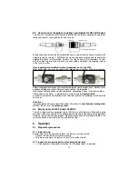
Two hoses (each 0.5 m long) are fitted to the device; they are connected with the pump
power pack via a hose pair (5 m / 10 m / 20 m, as is necessary). All hoses are colour
marked and have rapid action couplings so that they can be connected without the risk
of mix-up:

HP = High pressure ——> red,

R = reflux ——> blue.

Summary of Contents for LSI 400

Page 1: ...ssue08 2006 replaces 8 2002 1 Blade 2 Central bolt with self locking nut 3 Side handle 4 Electric push buttons 5 Rear handle 6 Hydraulic hose pair 0 5 m USA 3 m 7 Electric cable 0 5 m USA 3 m 8 Electr...

Page 2: ...ctions 4 4 Maintenance and servicing instructions 5 5 Safety instructions for hose lines 6 6 Indented use 8 7 Description 8 8 Connection of the devices 9 9 Operation 10 10 Dismantling of the device St...

Page 3: ...suitable for underwater use up to 40 m 1 6 Devices with cylinder bottom are intended for externally controlled processes They are mainly used on robots cranes or other manipulators 1 7 The manufacture...

Page 4: ...s Immediately report changes detected including changes to its operation to the appropriate office If necessary immediately shut off and secure the device Check all hydraulic and electrical lines hose...

Page 5: ...detergents Use a fibre free cloth and ensure thorough cleanliness especially when rebuilding 4 3 When dismantling the device ensure that all escaping hydraulic fluid is collected that it does not ent...

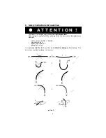
Page 6: ...t with the following fluids the hoses must immediately be cleaned acids soaps solutions diluted alcohol and fuels battery acids and ATF phosphate esters It is also essential that the hose lines are ch...

Page 7: ...pressure medium igniting close to a igniting source The danger can be avoided for example with protective coverings or shields 5 2 1 Beware of hairline tears Escaping high pressure oil can cause serio...

Page 8: ...the fittings which alleviates the function and stability of the fittings or the hose fittings connection Corroded fittings or metal inserts which alleviates the stability Storage times and period of u...

Page 9: ...ved to avoid any risk for persons and the device The device must be fitted swivelling around its longitudinal axis made possible by means of an axis of rotation on the robot or an adequate rotor sleev...

Page 10: ...ction has been made and locked Uncoupling is done in the reverse order Connection of the hoses is possible only when they are depressurized In order to prevent contamination of the tool lines protect...

Page 11: ...as possible to the blade fulcrum On cutting the gap between the blade tips must not be larger than 3 mm Risk of blade fracture 9 3 Cutters LSI 600 E 400 E By pushing the buttons 4 see cover page the...

Page 12: ...ck must be carried out at least once a year A function test must be accomplished every 500 operating hours or if there are doubts about the safety or reliability clean first if dirty Visual inspection...

Page 13: ...blue return hose has a safety coupling quick connect plug coloured yellow Undesired overpressure approx 1 5 MPa is automatically released via this plug oil escapes as well this is not a malefunction...

Page 14: ...ical parts under the hand guard of the device Moveable parts of the device could be blocked as a result and even be destroyed The device must be checked for dirt and impurities in the mechanical part...

Page 15: ...ing the cutters used oil with fresh oil must be avoided because of impurity Procedure The cutter is in closed retracted position Change oil of the pump Unscrew return hose on the pump for hose connect...

Page 16: ...h actuation for manual operation The hand guard protects the operator against injuries resulting caused by the moving parts In case of damage the hand guard must be replaced Procedure Unscrew handle r...

Page 17: ...onnected power pack operating Air in the hydrallic system Thorougly vent pump unit No pressure build up Insufficient oitl in the hand or motor pump Pump not ventilated after oil change Refill oil an v...

Page 18: ...20 22 14 3 Control voltage with integral switch V 24 Protective system switch cable plug IP 54 max operating pressure MPa 50 usable oil quantity l1 0 20 Opening distances and forces Measuring point Ma...

Page 19: ...is 55 C Type LSI 600 600E LSI 400 400E Central bolt M 27 x 1 5 SW 41 Torque Nm 130 10 Range of oil temperature Viscosity rating Remarks A 24 30 C HL 5 B 18 50 C HLP 10 C 8 75 C HLP 22 D 5 80 C HLP 32...

Page 20: ...s 1 risk of breakage Remark The bolts are freely acces sible when the cutter arms are closed I 2 3 4 8 j 1 Cutter blades 2 Center bolt with selfsecuring nut 3 Bearing bolt for lever 4 Lever 5 Bearing...

Page 21: ...inder body including V841 50 1290 11 Dichtung sealing AnschluBnippel M14x1 5 M12s1 S inklusive connection plug Mt4xl 5 MI 2s1 5 nk uding V84126 5102 35 Oichtring sealing ring Schraubkappe screw cap 0...

Page 22: ...Spare parts flat I 84112 5303 88 LUI 4S Recycling Aggregat P06 LSI mit Magnetvenhil Ausgabe I Issue 05 05 Recycling Power package P06 LSI with solenoid valve Seite I page 1 gOltig f r P06 LSI 510115 6...

Page 23: ...41 1210707 Wegesitzventll Ft 1 WG115 VB11 way seat valve R 1 WG230 VB11 V84112 5699 02 Wegesitzventii A 1 WG230 VB11 way seat valve R 1 WG230 VB11 V84112 5640 02 Wegesitzventil F 1 WG11 5 VB11 way sea...

Page 24: ...3 c xI z1 1 9 I _ I...

Page 25: ...Opening Hydraulic cylinder Culling...

Page 26: ...Hydraulic diagram T A...

Reviews: