background image

27

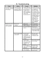
Fault

Check

Cause

Solution

Blade arms do 

not move when 

operated.

Battery fully 

charged?

Battery flat

Charge battery

Battery defective

Replace battery

Power supply cable 

connected?

Power supply cable 

defective

Replace power 

supply cable

Device defective

Repair by an 

authorized dealer, by 

personnel specially 

trained by LUKAS, 

or by LUKAS itself

Device does not 

perform at its given 

power

Device defective

Repair by an 

authorized dealer, by 

personnel specially 

trained by LUKAS, 

or by LUKAS itself

Following release, 

the star grip 

doesn’t return to 

the central position

Casing damaged or 

star grip operation 

not working 

smoothly?

Damage to the 

torsion spring for 

reset

Repair by an 

authorized dealer, 


by personnel 

specially trained 

by LUKAS, or by 

LUKAS itself

Soiled valve or star 

grip

Defective valve
Other mechanical 

damage (e.g. star 

grip)

Hydraulic fluid 

leaking from the 

piston rod

Defective rod seal

Repair by an 

authorized dealer, 


by personnel 

specially trained 

by LUKAS, or by 

LUKAS itself

Damage to the 

piston

The useful 

operating time 

between the 

individual charging 

cycles is less than 

5 minutes, despite 

charging the 

batteries according 

to the instructions.

Battery defective

Replace battery

Summary of Contents for S 312 E2

Page 1: ...172022085 EN replaces 09 2017 Edition 01 2018 Instruction manual for rescue equipment eDRAULIC cutters Translation of the original instruction manual S 700 E2 S 788 E2 S 312 E2 S 377 E2 ...

Page 2: ...2 5 1 Battery or power supply for eDRAULIC device 12 5 2 Operating the star grip 13 6 Cutting 14 6 1 Safety notes 14 6 2 Cutting 15 7 Dismantling the equipment deactivation following operation 16 8 Maintenance and service 17 8 1 Oil change 17 8 2 Overview of eDRAULIC cutting tools 18 8 3 Protective equipment 19 8 4 Checking the filter in the battery shaft 19 9 Repairs 20 9 1 General information 20...

Page 3: ...and storage temperature ranges 31 11 4 Oscillation vibration 31 11 5 Torques for central bolts 31 11 6 Cutting performance 32 11 7 Datasheets for the product performance 33 12 EC Declaration of Conformity 37 13 Accessories 38 13 1 Batteries 38 13 2 Battery charger 39 13 3 Power supply 39 14 Instructions regarding disposal 40 Content Page ...

Page 4: ... danger and the possible consequences 1 Danger classifications Pictogram Damage injury to Keyword Definition Consequences Persons DANGER Immediate danger Death or severe injury WARNING Potentially dangerous situation Potential death or serious injury CAUTION Less dangerous situation Minor or slight injury Property ATTENTION Risk of damage to property environment Damage to the equipment damage to t...

Page 5: ...efore they use the equipment and carefully follow them We further recommend that you have a qualified trainer show you how to use the product WARNING CAUTION The operating instructions for accessories must also be taken into account Even if you have already received instructions on how to use the equipment you should still read through the following safety instructions again WARNING CAUTION Please...

Page 6: ...always be complete and in a legible condition Any mode of operation which compromises the safety and or stability of the device is forbidden Repairs to the equipment may only be carried out by a trained service technician with specific knowledge of the device Safety devices may never be disabled Only genuine LUKAS accessories and spare parts are to be used for repairs Before switching on starting ...

Page 7: ...nt always ensure that the accessories are positioned in such a way that they cannot cause an accident Always keep these operating instructions easily accessible at the place of operation Ensure the proper disposal of all removed parts left over oil and hydraulic fluid as well as packaging materials The eDRAULIC devices have an IP54 protection class They are suitable for use in wet weather conditio...

Page 8: ...nd are to be implemented in addition to the operating instructions WARNING CAUTION ATTENTION The device is intended exclusively for the purpose stated in the operating instructions see chapter Proper Use Any other use is not in accordance with its designated purpose The manufacturer supplier is not liable for any damage resulting from improper use The user bears sole responsibility for such use Pr...

Page 9: ...e excluded that the device could trigger an explosion that working with the device could trigger an explosion e g sparks may result from cutting an object The responsibility for explosion prevention or for ruling out work with an eDRAULIC device with the operator of the device or with the person responsible at the place of use When working in areas at risk of explosion all applicable legal nationa...

Page 10: ... body of the tool They are then automatically locked into position You can extend the operating time of your eDRAULIC device by using several batteries The batteries can be recharged after use using a suitable external charger If you are making use of an external power supply the device can be used for an almost unlimited time This time is only limited by the external energy source and the overhea...

Page 11: ...ices 1 Star grip 2 Main switch 3 Quick exchange battery or power supply 4 Release button for battery and power supply 5 Handle 6 Ventilation slots 7 Blade arms 8 Pivot bolt with secured nut 9 Plastic housing 10 Tool body 11 Protective cover 12 Light S 700 E2 S 788 E2 S 312 E2 S 377 E2 ...

Page 12: ...grip 5 1 Battery or power supply for eDRAULIC device 5 Operation Commissioning Before initial operation the battery where used of the rescue device must be fully loaded using the external charger 4 3 Hydraulic circuit diagram A B cutting opening Below a simplified hydraulic ram representing the tool is depicted A tool B star grip valve ...

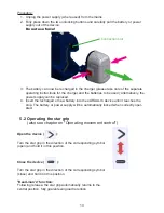
Page 13: ...harged or new battery into the eDRAULIC device until it reaches the stop The battery or power supply will be automatically locked when correctly oper ated Connection slot Open the device Turn the star grip in the direction of the corresponding symbol open and hold it in this position Close the device Turn the star grip in the direction of the corresponding symbol close and hold it in this position...

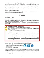
Page 14: ...explosions must be observed without restriction The following are to be worn when working with the rescue equipment protective clothing safety helmet with visor or protective goggles protective gloves and if necessary ear protection Before operating the rescue device you should ensure that no participants or bystanders are at risk from the movements of the rescue device or from flying fragments Av...

Page 15: ...eces of the vehicle to break off or fly off posing a danger to persons Those not involved in the rescue operation should therefore keep at a safe distance appropriate to the situation Any trapped or enclosed persons must be protected 6 2 Cutting The blades should be positioned at a 90 angle to the object to be cut if possible RIGHT WRONG 12 9 3 15 15 90 Higher cutting capacities can be achieved by...

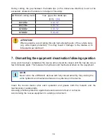
Page 16: ...88 E2 5 0 20 7 Dismantling the equipment deactivation following operation Once work has been completed the device arms should be closed until the tips are only a few millimeters apart This relieves the hydraulic and mechanical strain on the equipment Clean the rescue device after each operation and grease both the metallic and the mechanically movable parts Greasing provides protection against exc...

Page 17: ...re be any doubt regarding the safety or reliability of the equipment Please also observe the relevant valid national and international regulations pertaining to service intervals of rescue equipment In the Federal Republic of Germany regular safety inspections according to the regulations of the Gesetzlichen Unfallversicherung GUV connoted Legal accident insurance are mandatory ATTENTION Clean off...

Page 18: ... surfaces Cutting surfaces fit on top of each other without making contact The sliding plates bolts and retaining rings of the blade arms are in place and in good condition Illumination of main switch work area and connection shaft fully functional Battery and power supply Casing undamaged Electrical contact surfaces clean and undamaged Cable undamaged Battery ies fully charged when used Charging ...

Page 19: ...r after use in a dusty environment The filter can be checked from the outside if the mains unit or battery is removed see illustrations below If the filter is severely contaminated it will need to be replaced Procedure 1 Tilt the respective device as shown in the illustration 2 Remove the battery or the power supply 3 Remove the filter grid by activating the release hook 4 Replace the dirty filter...

Page 20: ...all components are particularly clean as dirt can damage the rescue equipment WARNING CAUTION PLEASE NOTE Protective clothes must be worn when repairs are being carried out as the devices may also be pressurized when not in operation ATTENTION Because LUKAS rescue devices are designed for highest performance only components specified in the spare parts list for the appropriate equipment may be rep...

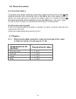
Page 21: ...ot on the battery and on the power supply In case of doubt contact your authorized LUKAS dealer or LUKAS directly 9 2 2 Function and load test If there is any doubt regarding the safety or reliability of a device a function and stress test must also be performed LUKAS offers appropriate test equipment for this 9 3 1 Replacing the blade protective cover and hand grip of the cutter S 700 E2 S 788 E2...

Page 22: ...necessary loosen the hand grip and move it backwards to obtain sufficient space to pull it out 3 Move the blade arms on the until bolt E is easily accessible Now switch off the device and remove the battery or unplug the power supply from the device Work steps 1 First of all carefully clean the rescue equipment CAUTION PLEASE NOTE When operating the device with the hand guard removed there is an i...

Page 23: ...lled out forwards NOTE The torque required can be taken from the spare parts list of your particular unit 7 The work steps must be carried out in reverse order to fit the new parts 5 Remove the locking rings M and push the pin N out You can then pull out the blades O and the slide plates P ATTENTION Apply LUKAS special grease to all sliding surfaces N P N M O M H G J K L ...

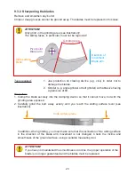
Page 24: ...ade arm Pivot point Blade arm Slide surface plane ATTENTION If you have not maintained the smoothness or incline the proper operation of the blade is no longer guaranteed and the blades must be replaced In addition when grinding you must make sure that the inclination of the cutting surface in the direction of the blade arm movement is not changed Check the incline and smoothness of the ground sur...

Page 25: ...c must be replaced Procedure 1 Remove damaged and or illegible decals 2 Clean surfaces with industrial alcohol 3 Affix new decals Take care to affix the labels in the correct positions If this is no longer known you should ask your authorized LUKAS dealer or contact LUKAS directly ...

Page 26: ... the battery may be briefly unplugged and replugged again Blade arms move slowly or jerkily when operated Battery fully charged Battery flat Charge battery Battery defective Replace battery Air in the hydraulic system Repair by an authorized dealer by personnel specially trained by LUKAS or by LUKAS itself Power supply cable connected Power supply not properly connected to the eDRAULIC device not ...
Page 27: ...Following release the star grip doesn t return to the central position Casing damaged or star grip operation not working smoothly Damage to the torsion spring for reset Repair by an authorized dealer by personnel specially trained by LUKAS or by LUKAS itself Soiled valve or star grip Defective valve Other mechanical damage e g star grip Hydraulic fluid leaking from the piston rod Defective rod sea...

Page 28: ... following tables The values may also differ because of reading inaccuracies and or tolerances in the measuring equipment used Operating pressure S 312 E2 70 MPa S 377 E2 70 MPa S 700 E2 80 MPa S 788 E2 70 MPa Contact an authorised LUKAS dealer or the LUKAS Customer Service Department directly if the malfunctions cannot be rectified The address for the LUKAS Customer Service department is LUKAS Hy...

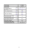
Page 29: ... 6 x 9 3 x 11 1 36 8 x 9 3 x 11 1 36 2 x 11 7 x 10 3 Min cutting opening mm 162 206 192 in 6 4 8 11 7 6 Mass excl battery kg 18 5 19 3 21 8 lbs 40 8 42 6 48 1 Nominal electrical voltage with power supply V DC 25 Nominal electrical voltage with lithium ion battery V DC 25 2 Protection category IP 54 Cutting Class EN 13204 I I J Classification NFPA 1936 A7 B8 C7 D7 E7 A7 B8 C7 D7 E8 A8 B9 C8 D9 E9 ...

Page 30: ...281 in 38 9 x 10 5 x 11 1 Min cutting opening mm 200 in 7 97 Mass excl battery kg 22 7 lbs 50 0 Nominal electrical voltage with power supply V DC 25 Nominal electrical voltage with lithium ion battery V DC 25 2 Protection category IP 54 Cutting Class EN 13204 K Classification NFPA 1936 A8 B9 C8 D9 E9 ...

Page 31: ...re C F 20 55 4 131 Storage temperature device not in operation C F 30 60 22 140 11 4 Oscillation vibration The total oscillation value vibration value to which the upper limbs are exposed is usually below 2 5 m s Higher values may be measured for short periods as a result of interaction with the materials to be processed The oscillations vibrations were determined in accordance with DIN EN ISO 206...

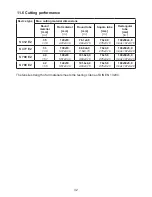
Page 32: ...00x50x4 0 3 94x1 97x0 16 S 377 E2 33 1 30 130x10 5 12x0 39 88 9x4 0 3 5x0 16 70x4 0 2 76x0 16 100x50x5 0 3 94x1 97x0 20 S 700 E2 40 1 57 140x10 5 51x0 39 101 6x4 0 4 00x0 16 70x5 0 2 76x0 20 100x50x5 0 3 94x1 97x0 20 S 788 E2 42 1 65 140x10 5 51x0 39 101 6x4 0 4 00x0 16 70x5 0 2 76x0 20 100x50x5 0 3 94x1 97x0 20 The tensile strength of all materials meets the testing criteria of DIN EN 13204 11 6 ...

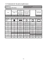
Page 33: ...Square tube 5 Rectangular tube Category letter A 14 30 x 5 21 3 x 2 3 B 16 40 x 5 26 4 x 2 3 C 18 50 x 5 33 7 x 2 6 35 x 3 D 20 60 x 5 42 6 x 2 6 40 x 4 50 x 25 x 2 5 E 22 80 x 8 48 3 x 2 9 45 x 4 50 x 30 x 3 0 F 24 80 x 10 60 3 x 2 9 50 x 4 60 x 40 x 3 0 G 26 100 x 10 76 1 x 3 2 55 x 4 80 x 40 x 3 0 H 28 110 x 10 76 1 x 4 0 60 x 4 80 x 40 x 4 0 I 32 120 x 10 88 9 x 4 0 60 x 5 80 x 40 x 5 0 J 36 1...

Page 34: ...terial 3 Round tube 4 Square tube 5 Rectangular tube Category letter A 14 30 x 5 21 3 x 2 3 B 16 40 x 5 26 4 x 2 3 C 18 50 x 5 33 7 x 2 6 35 x 3 D 20 60 x 5 42 6 x 2 6 40 x 4 50 x 25 x 2 5 E 22 80 x 8 48 3 x 2 9 45 x 4 50 x 30 x 3 0 F 24 80 x 10 60 3 x 2 9 50 x 4 60 x 40 x 3 0 G 26 100 x 10 76 1 x 3 2 55 x 4 80 x 40 x 3 0 H 28 110 x 10 76 1 x 4 0 60 x 4 80 x 40 x 4 0 I 32 120 x 10 88 9 x 4 0 60 x ...

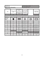
Page 35: ...terial 3 Round tube 4 Square tube 5 Rectangular tube Category letter A 14 30 x 5 21 3 x 2 3 B 16 40 x 5 26 4 x 2 3 C 18 50 x 5 33 7 x 2 6 35 x 3 D 20 60 x 5 42 6 x 2 6 40 x 4 50 x 25 x 2 5 E 22 80 x 8 48 3 x 2 9 45 x 4 50 x 30 x 3 0 F 24 80 x 10 60 3 x 2 9 50 x 4 60 x 40 x 3 0 G 26 100 x 10 76 1 x 3 2 55 x 4 80 x 40 x 3 0 H 28 110 x 10 76 1 x 4 0 60 x 4 80 x 40 x 4 0 I 32 120 x 10 88 9 x 4 0 60 x ...

Page 36: ...terial 3 Round tube 4 Square tube 5 Rectangular tube Category letter A 14 30 x 5 21 3 x 2 3 B 16 40 x 5 26 4 x 2 3 C 18 50 x 5 33 7 x 2 6 35 x 3 D 20 60 x 5 42 6 x 2 6 40 x 4 50 x 25 x 2 5 E 22 80 x 8 48 3 x 2 9 45 x 4 50 x 30 x 3 0 F 24 80 x 10 60 3 x 2 9 50 x 4 60 x 40 x 3 0 G 26 100 x 10 76 1 x 3 2 55 x 4 80 x 40 x 3 0 H 28 110 x 10 76 1 x 4 0 60 x 4 80 x 40 x 4 0 I 32 120 x 10 88 9 x 4 0 60 x ...

Page 37: ...37 12 EC Declaration of Conformity ...

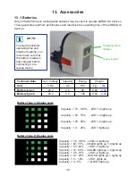
Page 38: ... lights up Capacity 62 75 4th LED lights up 1 3 lights up Capacity 50 62 LED 1 3 lights up Capacity 37 50 3rd LED lights up 1 2 lights up Capacity 25 37 LED 1 2 lights up Capacity 12 25 2nd LED lights up 1 lights up Capacity 5 12 LED 1 lights up Capacity 0 5 1st LED lights up Battery Type 2 Display code Battery Type 1 Display code Capacity 75 100 LED 1 4 lights up Capacity 50 75 LED 1 3 lights up ...

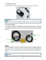
Page 39: ...directly connected to the power grid The power supply converts the alternating current from the power grid into direct current which means that it can be used instead of the battery Structure There is an adapter on one side of the power supply which can be simply inserted into the connection slot of the devices and locked The other side has a mains plug Both are connected by a cable The mains plug...

Page 40: ...hould always be disposed of in an environmentally compatible way Only for EU countries Do not dispose of electrical equipment with your household waste According to the European Directive 2002 96 EC governing electrical and electronic waste and their application in national legislation old electrical equipment must be separately collected and recycled in an environmentally compatible manner Please...

Reviews: