7.25
Model 644E-42/944E-42
Rev. 6/04
Engine: Cummins 4BT 3.9, B4.5T and QSB 4.5T
c. Cleaning and Drying
If contaminated fuel or foreign material is in the tank, the
tank can usually be cleaned. Replace a leaking or
damaged tank. DO NOT attempt to repair, plug or patch
a leaking or damaged fuel tank. The tank is manufactured
using an injection molding process and cannot be
repaired. Contact JLG Service Department at:
(877) 554-5438 or (717) 485-6657
To clean the fuel tank:
1. Have a dry chemical (Class B) fire extinguisher near
the work area.
2. Invert and tilt the tank from side to side. Safely drain
any fuel into a suitable container. Dispose of fuel
properly.
3. Clean the fuel tank with a high-pressure washer, or
flush the tank with hot water for five minutes. Invert
the tank, tilt it from side to side, and drain the water.
4. If necessary, add a diesel fuel emulsifying agent to
the tank. Refer to the engine manufacturer for the
correct emulsifying agent-to-water mixture ratio.
Refill the tank with water, and agitate the mixture for
10 minutes. Drain the tank completely.
5. Refill the fuel tank with water until it overflows.
Completely flush the tank with water. Empty the tank
and allow it to dry completely.
d. Inspection
1. Inspect the fuel tank thoroughly for any cracks,
slices, leaks or other damage. Replace a leaking or
damaged tank. DO NOT attempt to repair, plug or
patch a leaking or damaged fuel tank. The tank is
manufactured using an injection molding process
and cannot be repaired. Contact JLG Service
Department at: (877) 554-5438 or (717) 485-6657
2. With the fuel tank removed from the vehicle, plug all
openings except one elbow fitting. Install the elbow
fitting and apply approximately 1 to 1-1/2 psi
(7 to 10 kPa) of air pressure through the elbow.
Check the tank for leaks by applying a soap solution
to the exterior of the tank, or by submerging the tank
in water and looking for bubbles to appear at the
cracked or damaged area.
e. Assembly and Replacement
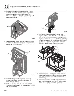
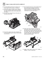
1. Install the fuel sender, with gasket, (6) to the fuel
tank (1). Secure with the five previously removed
capscrews (5), and torque to 1.5-2.5 lb-ft (2-3 Nm).
Do not overtighten.
2. Install the 3/8" NPT square head drain plug (7).
3. Replace the fuel tank (1) onto tank support (part of
cab structure.) Attach the fuel level gauge wire (4).
Secure fuel tank retaining panel (2), with two (3)
previously removed capscrews. Torque capscrews to
38-59 lb-ft (50-80 Nm).
4. Reconnect the fuel hoses (8 and 9). Torque the hose
clamps to 4 lb-in (0,46 Nm).
7.8.3
Fuel Level Sender and Gauge
The fuel level sender and gauge assembly is described in
Section 9.14.17, “Fuel Level Gauge and Fuel Level
Sender.”
WARNING:
NEVER drain or store fuel in
an open container due to the possibility of
explosion or fire. Discard the fuel in an
approved manner.
Summary of Contents for 944E-42
Page 1: ......
Page 2: ......
Page 14: ...Safety Practices 1 8 Model 644E 42 944E 42 Rev 6 04 This Page Intentionally Left Blank...
Page 102: ...Boom 3 56 Model 644E 42 944E 42 Rev 6 04 This Page Intentionally Left Blank...
Page 139: ...4 37 Model 644E 42 944E 42 Rev 6 04 Cab and Covers This Page Intentionally Left Blank...
Page 144: ...Cab and Covers 4 42 Model 644E 42 944E 42 Rev 6 04 This Page Intentionally Left Blank...
Page 265: ...8 15 Model 644E 42 944E 42 Rev 6 04 Hydraulic System This Page Intentionally Left Blank...
Page 269: ...8 19 Model 644E 42 944E 42 Rev 6 04 Hydraulic System This Page Intentionally Left Blank...
Page 273: ...8 23 Model 644E 42 944E 42 Rev 6 04 Hydraulic System This Page Intentionally Left Blank...
Page 277: ...8 27 Model 644E 42 944E 42 Rev 6 04 Hydraulic System This Page Intentionally Left Blank...
Page 281: ...8 31 Model 644E 42 944E 42 Rev 6 04 Hydraulic System This Page Intentionally Left Blank...
Page 285: ...8 35 Model 644E 42 944E 42 Rev 6 04 Hydraulic System This Page Intentionally Left Blank...
Page 289: ...8 39 Model 644E 42 944E 42 Rev 6 04 Hydraulic System This Page Intentionally Left Blank...
Page 293: ...8 43 Model 644E 42 944E 42 Rev 6 04 Hydraulic System This Page Intentionally Left Blank...
Page 297: ...8 47 Model 644E 42 944E 42 Rev 6 04 Hydraulic System This Page Intentionally Left Blank...
Page 301: ...8 51 Model 644E 42 944E 42 Rev 6 04 Hydraulic System This Page Intentionally Left Blank...
Page 407: ...8 157 Model 644E 42 944E 42 Rev 6 04 Hydraulic System This Page Intentionally Left Blank...
Page 425: ...8 175 Model 644E 42 944E 42 Rev 6 04 Hydraulic System This Page Intentionally Left Blank...
Page 501: ...8 251 Model 644E 42 944E 42 Rev 6 04 Hydraulic System MT1950 2 3 4 5 6 7 8 5 5...
Page 507: ...8 257 Model 644E 42 944E 42 Rev 6 04 Hydraulic System MT1950 1 2 3 4 5 6 7 4 4...
Page 508: ...Hydraulic System 8 258 Model 644E 42 944E 42 Rev 6 04 This Page Intentionally Left Blank...
Page 525: ...9 17 Model 644E 42 944E 42 Rev 6 04 Electrical System This Page Intentionally Left Blank...
Page 554: ...Electrical System 9 46 Model 644E 42 944E 42 Rev 6 04 This Page Intentionally Left Blank...
Page 759: ...10 3 Model 644E 42 944E 42 Rev 6 04 Stabil TRAK System This Page Intentionally Left Blank...
Page 765: ...10 9 Model 644E 42 944E 42 Rev 6 04 Stabil TRAK System This Page Intentionally Left Blank...
Page 785: ...10 29 Model 644E 42 944E 42 Rev 6 04 Stabil TRAK System This Page Intentionally Left Blank...
Page 800: ...Stabil TRAK System 10 44 Model 644E 42 944E 42 Rev 6 04 This Page Intentionally Left Blank...
Page 832: ...Transfer Carriage 11 32 Model 644E 42 944E 42 Rev 6 04 This Page Intentionally Left Blank...
Page 840: ...12 8 Model 644E 42 944E 42 Rev 6 04 Index...
Page 841: ...Accident Prevention Tags OS2180 8990403 Origin 5 00 Accident Prevention Tags...
Page 842: ...Accident Prevention Tags OS2180 8990403 Origin 5 00...
Page 843: ......
Page 844: ......


