8.167
Model 644E-42/944E-42
Rev. 6/04
Hydraulic System
b. Tools Required for Pump Repair
The following tools are required for servicing the pump:
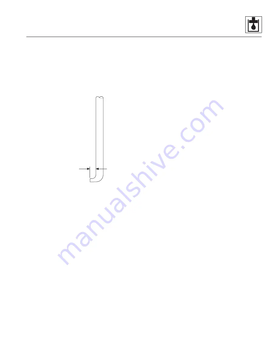
1. A seal removal tool made by heating the tip of a
quality forged screwdriver and bending it. Grind off
the tip to fit the notch behind the pump shaft seal.
After bending and grinding the screwdriver, the
measurement between the tip and the shaft (16)
should be 1/4".
2. A lip seal installation bar made from 1-3/4"
(44,5 mm) diameter round steel bar stock, 2"
(50,8 mm) long. Grind the edges slightly to form the
tool.
3. The following tools will also be required:
• Arbor Press
• Clean, Lintless Cloths
• Soft Hammer
• Medium-Grit Carborundum Stone
• Oil and Graphite Grease
• Internal Snap-Ring Pliers
• Small Screwdriver
• Torque Wrench
• Vise with 8" Minimum Open Spread
c. General Repair Precautions
1. To facilitate repair of the pump and before any work
is done, read and understand all of the steps used in
the disassembly and assembly instructions.
2. Perform procedures in a clean area. It is important to
service hydraulic equipment in as clean an
environment as possible.
3. If it becomes necessary to separate the sections,
use a plastic mallet to separate the sections. NEVER
pry the sections apart with a pry tool or screwdriver.
4. The front and rear covers, center sections and
ported section all have notches cast into the edges
for alignment when reassembling the sections. By
lining up the notches of these parts the pump will be
properly assembled and proper rotation of the pump
will be assured. It is still recommended that the parts
be marked on the side to ensure proper reassembly.
5. Gears are closely matched sets that wear in
together. Keep gears together as sets when
removing them from a unit. Handle gears with care
to avoid damaging the journals or teeth. Avoid
touching gear journals. Always replace matched
parts as a set.
6. To help prevent damage, DO NOT grip machined
surfaces in a vise.
7. If parts are difficult to fit together during assembly,
tap gently with a soft hammer. NEVER use an iron or
steel hammer to tap parts.
8. NEVER hammer bushings into bores. Use an arbor
press and bushing drivers of appropriate sizes to
install bushings.
MA0802
16
Summary of Contents for 944E-42
Page 1: ......
Page 2: ......
Page 14: ...Safety Practices 1 8 Model 644E 42 944E 42 Rev 6 04 This Page Intentionally Left Blank...
Page 102: ...Boom 3 56 Model 644E 42 944E 42 Rev 6 04 This Page Intentionally Left Blank...
Page 139: ...4 37 Model 644E 42 944E 42 Rev 6 04 Cab and Covers This Page Intentionally Left Blank...
Page 144: ...Cab and Covers 4 42 Model 644E 42 944E 42 Rev 6 04 This Page Intentionally Left Blank...
Page 265: ...8 15 Model 644E 42 944E 42 Rev 6 04 Hydraulic System This Page Intentionally Left Blank...
Page 269: ...8 19 Model 644E 42 944E 42 Rev 6 04 Hydraulic System This Page Intentionally Left Blank...
Page 273: ...8 23 Model 644E 42 944E 42 Rev 6 04 Hydraulic System This Page Intentionally Left Blank...
Page 277: ...8 27 Model 644E 42 944E 42 Rev 6 04 Hydraulic System This Page Intentionally Left Blank...
Page 281: ...8 31 Model 644E 42 944E 42 Rev 6 04 Hydraulic System This Page Intentionally Left Blank...
Page 285: ...8 35 Model 644E 42 944E 42 Rev 6 04 Hydraulic System This Page Intentionally Left Blank...
Page 289: ...8 39 Model 644E 42 944E 42 Rev 6 04 Hydraulic System This Page Intentionally Left Blank...
Page 293: ...8 43 Model 644E 42 944E 42 Rev 6 04 Hydraulic System This Page Intentionally Left Blank...
Page 297: ...8 47 Model 644E 42 944E 42 Rev 6 04 Hydraulic System This Page Intentionally Left Blank...
Page 301: ...8 51 Model 644E 42 944E 42 Rev 6 04 Hydraulic System This Page Intentionally Left Blank...
Page 407: ...8 157 Model 644E 42 944E 42 Rev 6 04 Hydraulic System This Page Intentionally Left Blank...
Page 425: ...8 175 Model 644E 42 944E 42 Rev 6 04 Hydraulic System This Page Intentionally Left Blank...
Page 501: ...8 251 Model 644E 42 944E 42 Rev 6 04 Hydraulic System MT1950 2 3 4 5 6 7 8 5 5...
Page 507: ...8 257 Model 644E 42 944E 42 Rev 6 04 Hydraulic System MT1950 1 2 3 4 5 6 7 4 4...
Page 508: ...Hydraulic System 8 258 Model 644E 42 944E 42 Rev 6 04 This Page Intentionally Left Blank...
Page 525: ...9 17 Model 644E 42 944E 42 Rev 6 04 Electrical System This Page Intentionally Left Blank...
Page 554: ...Electrical System 9 46 Model 644E 42 944E 42 Rev 6 04 This Page Intentionally Left Blank...
Page 759: ...10 3 Model 644E 42 944E 42 Rev 6 04 Stabil TRAK System This Page Intentionally Left Blank...
Page 765: ...10 9 Model 644E 42 944E 42 Rev 6 04 Stabil TRAK System This Page Intentionally Left Blank...
Page 785: ...10 29 Model 644E 42 944E 42 Rev 6 04 Stabil TRAK System This Page Intentionally Left Blank...
Page 800: ...Stabil TRAK System 10 44 Model 644E 42 944E 42 Rev 6 04 This Page Intentionally Left Blank...
Page 832: ...Transfer Carriage 11 32 Model 644E 42 944E 42 Rev 6 04 This Page Intentionally Left Blank...
Page 840: ...12 8 Model 644E 42 944E 42 Rev 6 04 Index...
Page 841: ...Accident Prevention Tags OS2180 8990403 Origin 5 00 Accident Prevention Tags...
Page 842: ...Accident Prevention Tags OS2180 8990403 Origin 5 00...
Page 843: ......
Page 844: ......


