Axles, Drive Shafts, Wheels, Tires and Brakes
5.8
Model 644E-42/944E-42
Rev. 6/04
b. Axle Inspection, Internal Service and Repair
Note: Detailed axle service instructions (covering axle,
brakes and wheel end safety, repair, disassembly,
reassembly, adjustment and troubleshooting information)
are provided in the ZF Axle Repair Manual, (944E Front)
Model MS-T 3060, JLG P/N 8990430 (ZF P/N 5871 560
002) and (944E Rear & 644E Front and Rear) Model
MS-T 3045, JLG P/N 8990419 (ZF P/N 5871 550 002).
The axle should be checked, serviced and repaired only
by experienced service technicians who are aware of all
safety instructions and particular component features.
c. Installation
The front and rear axle assemblies differ in that the front
axle assembly is equipped with a parking brake
mechanism and limited-slip feature; the rear axle has
neither. The steps below outline a typical axle installation
procedure, suitable for either the front or the rear axle
assembly.
1. Before proceeding, ensure that the vehicle will
remain in place during axle installation. Block the
front and rear of both tires on the axle that is already
installed on the vehicle.
2. If applicable, raise the vehicle using a suitable jack
or hoist. Place suitable supports beneath the frame
and lower the vehicle onto the supports, allowing
enough room for axle installation. Ensure that the
vehicle will remain in place during axle installation.
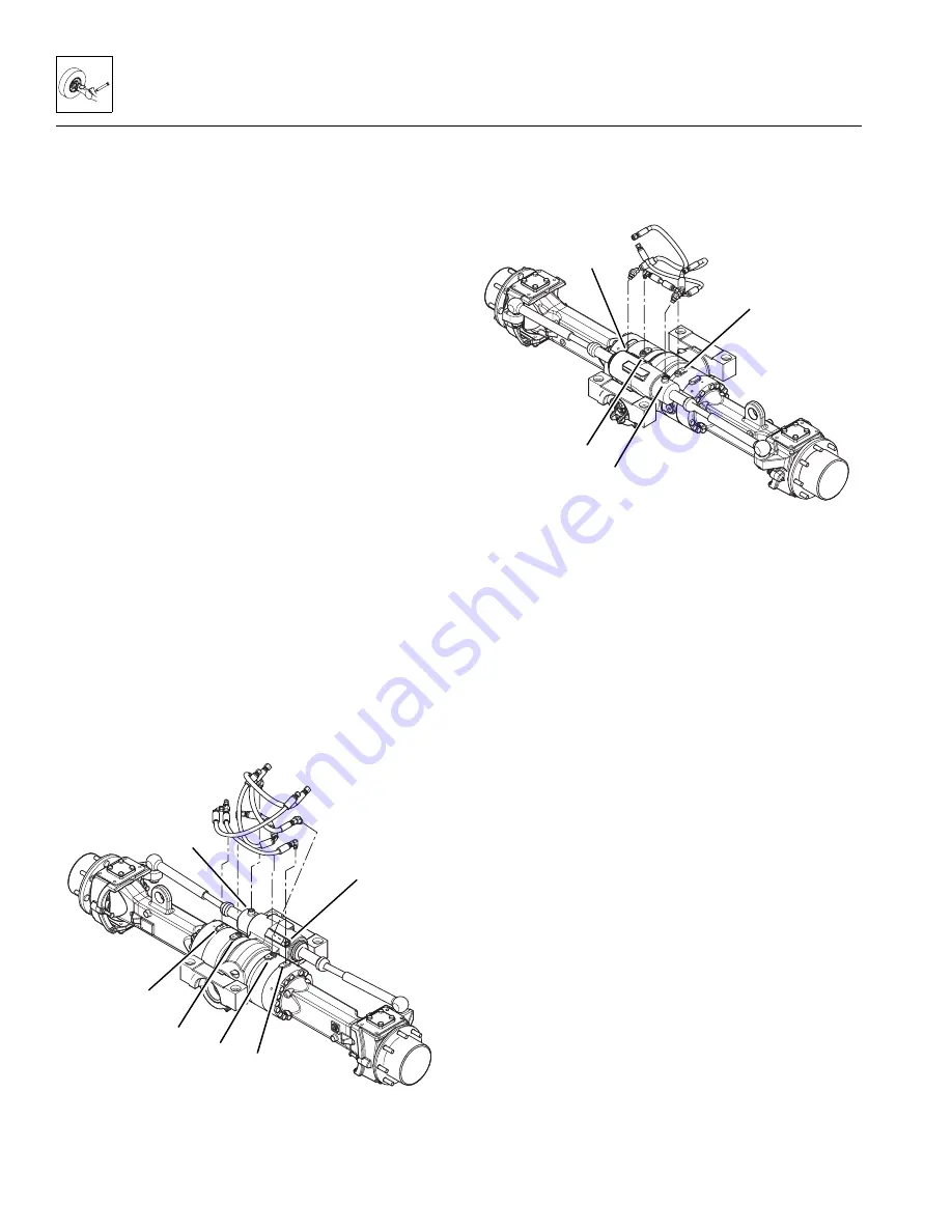
3. On the front axle, if applicable, uncap and install
the service brake (1), parking brake (2) and steering
hydraulic fittings (3) and hoses in their previously
marked positions.
4. On the rear axle, if applicable, uncap and install the
service brake (4) and steering hydraulic fittings (5)
and hoses in their previously marked positions.
5. Using a suitable jack, hoist or overhead crane and
sling, remove the axle (6-Front or 7-Rear) from its
support or holding stand. Balance the axle, and
prevent it from tipping, turning or falling while
positioning it beneath the vehicle. DO NOT raise or
otherwise disturb the vehicle while installing the axle.
Keep the axle supported and balanced on the jack,
hoist or overhead crane and sling throughout the
installation procedure.
Note: ALWAYS replace elastic locknuts with new elastic
locknuts to help ensure proper fastening.
Note: If you are installing the rear axle it may be easier
to install the capscrews if the transfer carriage was
moved all the way forward.
6. Coat the capscrews with anti-seize compound.
Install the four capscrews (8), four new elastic
locknuts (9), and eight hardened washers (10)
securing the front or rear axle supports to the vehicle
frame. Torque capscrews to 600-680 lb-ft (813-922
Nm).
MU1510
1
2
3
MU1520
4
5
Summary of Contents for 944E-42
Page 1: ......
Page 2: ......
Page 14: ...Safety Practices 1 8 Model 644E 42 944E 42 Rev 6 04 This Page Intentionally Left Blank...
Page 102: ...Boom 3 56 Model 644E 42 944E 42 Rev 6 04 This Page Intentionally Left Blank...
Page 139: ...4 37 Model 644E 42 944E 42 Rev 6 04 Cab and Covers This Page Intentionally Left Blank...
Page 144: ...Cab and Covers 4 42 Model 644E 42 944E 42 Rev 6 04 This Page Intentionally Left Blank...
Page 265: ...8 15 Model 644E 42 944E 42 Rev 6 04 Hydraulic System This Page Intentionally Left Blank...
Page 269: ...8 19 Model 644E 42 944E 42 Rev 6 04 Hydraulic System This Page Intentionally Left Blank...
Page 273: ...8 23 Model 644E 42 944E 42 Rev 6 04 Hydraulic System This Page Intentionally Left Blank...
Page 277: ...8 27 Model 644E 42 944E 42 Rev 6 04 Hydraulic System This Page Intentionally Left Blank...
Page 281: ...8 31 Model 644E 42 944E 42 Rev 6 04 Hydraulic System This Page Intentionally Left Blank...
Page 285: ...8 35 Model 644E 42 944E 42 Rev 6 04 Hydraulic System This Page Intentionally Left Blank...
Page 289: ...8 39 Model 644E 42 944E 42 Rev 6 04 Hydraulic System This Page Intentionally Left Blank...
Page 293: ...8 43 Model 644E 42 944E 42 Rev 6 04 Hydraulic System This Page Intentionally Left Blank...
Page 297: ...8 47 Model 644E 42 944E 42 Rev 6 04 Hydraulic System This Page Intentionally Left Blank...
Page 301: ...8 51 Model 644E 42 944E 42 Rev 6 04 Hydraulic System This Page Intentionally Left Blank...
Page 407: ...8 157 Model 644E 42 944E 42 Rev 6 04 Hydraulic System This Page Intentionally Left Blank...
Page 425: ...8 175 Model 644E 42 944E 42 Rev 6 04 Hydraulic System This Page Intentionally Left Blank...
Page 501: ...8 251 Model 644E 42 944E 42 Rev 6 04 Hydraulic System MT1950 2 3 4 5 6 7 8 5 5...
Page 507: ...8 257 Model 644E 42 944E 42 Rev 6 04 Hydraulic System MT1950 1 2 3 4 5 6 7 4 4...
Page 508: ...Hydraulic System 8 258 Model 644E 42 944E 42 Rev 6 04 This Page Intentionally Left Blank...
Page 525: ...9 17 Model 644E 42 944E 42 Rev 6 04 Electrical System This Page Intentionally Left Blank...
Page 554: ...Electrical System 9 46 Model 644E 42 944E 42 Rev 6 04 This Page Intentionally Left Blank...
Page 759: ...10 3 Model 644E 42 944E 42 Rev 6 04 Stabil TRAK System This Page Intentionally Left Blank...
Page 765: ...10 9 Model 644E 42 944E 42 Rev 6 04 Stabil TRAK System This Page Intentionally Left Blank...
Page 785: ...10 29 Model 644E 42 944E 42 Rev 6 04 Stabil TRAK System This Page Intentionally Left Blank...
Page 800: ...Stabil TRAK System 10 44 Model 644E 42 944E 42 Rev 6 04 This Page Intentionally Left Blank...
Page 832: ...Transfer Carriage 11 32 Model 644E 42 944E 42 Rev 6 04 This Page Intentionally Left Blank...
Page 840: ...12 8 Model 644E 42 944E 42 Rev 6 04 Index...
Page 841: ...Accident Prevention Tags OS2180 8990403 Origin 5 00 Accident Prevention Tags...
Page 842: ...Accident Prevention Tags OS2180 8990403 Origin 5 00...
Page 843: ......
Page 844: ......


