


Lumacell
Tel: (888) 552-6467 ext. 547 or 255
Fax: (888) 867-1565
www.lumacell.com
06/04 750.1048 Rev. B
1/4
LER3000 Series – Polyvinyl Exit Sign
LER3000 Series – Polyvinyl Exit Sign
AC/DC & Self-Powered Models
IMPORTANT SAFEGUARDS
When using electrical equipment, basic safety precautions should
always be followed including the following:
READ AND FOLLOW ALL SAFETY
INSTRUCTIONS
1. Do not let power supply cords touch hot surfaces.
2. Do not mount near gas or electric heaters.
3. Use caution when handling batteries. Avoid possible shorting.
4. Equipment should be mounted in locations and at heights where it
will not readily be subjected to tampering by unauthorized personnel.
5. The use of accessory equipment not recommended by the manufac-
turer may cause an unsafe condition.
6. Do not use this equipment for other than intended use.
7. All servicing should be performed by qualified service personnel.
SAVE THESE INSTRUCTIONS
Installation Instructions
1. Turn off unswitched AC power.
Canopy Mount
a. Remove canopy assembly from carton. Remove mounting plate
from canopy and retain securement screw.
b. Route unswitched AC circuit wires into the junction box and leave
6” of wire length.
c. Remove proper knockouts in canopy backplate for desired
mounting position.
For
Nexus
option, install the liquid tight fitting, provided with the
unit. For Ceiling mount, use the k’out located on side of the unit
(opposite side of the diagnostic display). For Side mount, use the
k’out located on top of the unit (see fig. 4).
d. Feed unswitched AC wires through large hole in canopy mount-
ing plate.
e. Make sure the securement screw is accessible (see fig.1 part #
13). Use existing screws in junction box to secure canopy back-
plate to the junction box.
f. Remove lens, exit panel and diffuser panel on the front of the unit
(use the supplied bit to remove the tamper-proof screws).
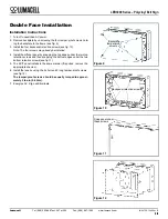
g. In order to access the knockouts of the frame, remove the 4 elec-
tronic module screw(s) holding the electronic module to the frame
and separate them (see fig.2).
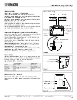
Figure 1
Part List
1. Tamper-proof screws short
(4 per lens)
2. Tamper-proof screws long
(2 per lens)
3. Lens
4. EXIT panel
5. Diffuser panel
6. Frame
7. Electronic module
8. Electronic module screws
(4)
9. Backplate (single face sign)
10. Backplate tamper-proof
screws (4)
11. Lock-nuts (2)
12. Gasket washer (2)
13. Canopy securement screw
14. Canopy
15. Nipple assembly (2)
16. Canopy backplate
17. Junction box screws (not
supplied)
18. Junction box (not supplied)
19. Nylon washer (2 for wall
mount)
20. Junction box gasket (for
wall mount)
Figure 2


