

LER3000 Series – Polyvinyl Exit Sign
2/4
Lumacell
Tel: (888) 552-6467 ext. 547 or 255
Fax: (888) 867-1565
www.lumacell.com
06/04 750.1048 Rev. B
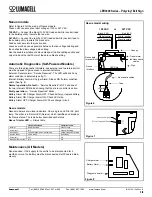
h. Determine which holes in the exit frame will be used for mounting
(see fig.1 & fig.3). Support frame by two blocks of wood, maxi-
mum one inch apart. Strike knockouts with a hammer and screw-
driver. Clear holes of burrs to allow proper assembly of nipple/
wire assembly.
i. Secure canopy to the frame using the provided nipple/wire
assembly. Make sure the gasket washers are between the can-
opy and frame, and the nuts inside the exit sign (see fig. 3).
j. Reassemble the electronic module inside the frame.
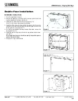
Wall Mount (Single Face Model Only)
a. Remove the backplate from the packaging. Determine the proper
knockouts to remove for mounting to a junction box (see fig.4).
For
Nexus
option, install the liquid tight fitting, provided with the
unit (see fig. 4).
b. Support area around knockouts with two blocks of wood. Strike
knockouts from the inside with a hammer and a screwdriver.
c. Mount parts 11, 12, 15, 17 & 19 to backplate, as shown in fig. 4,
and reinstall the backplate to the frame using the 4 tamper-proof
screws (use the supplied bit).
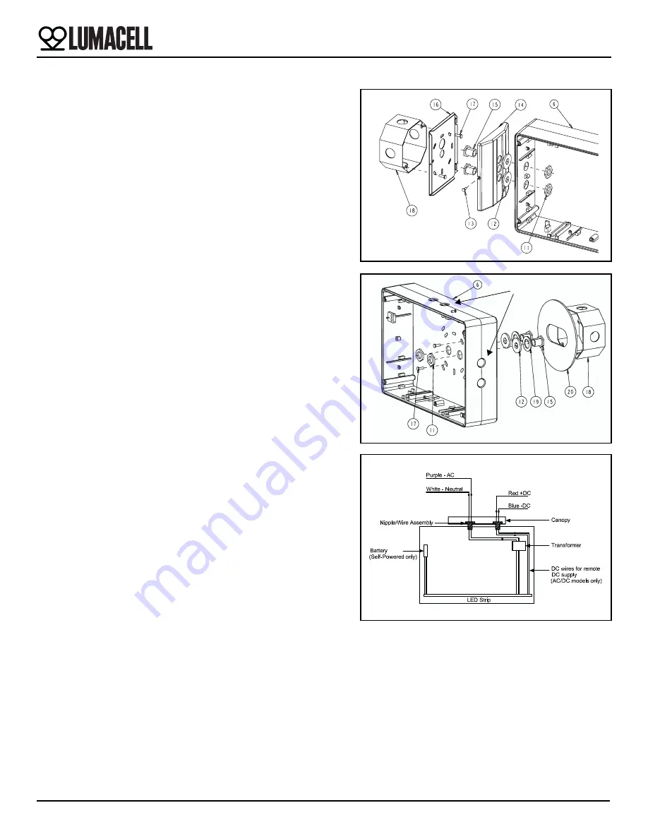
2.
Electrical connections:
Using the sealed AC nipple/wire assembly
(3 wires), connect one end to the transformer leads, inside the enclo-
sure, and the other end, to AC line voltage inside the junction box.
Connect the white lead to neutral and the purple lead to AC line volt-
age (the input is universal 110 to 347 VAC). (See fig. 5).
Optional:
For AC models used with DC remote power, the sealed
DC nipple/wire assembly (2 wires) will also need to be installed. One
end connects to the LED-STRIP leads, inside the enclosure, and the
other end to DC input inside the junction box. Connect the red lead
to positive, and the blue lead to the negative of the remote DC input
(See fig. 5).
3.
For canopy mount:
Attach the canopy backplate to the junction box
using the junction box screws. Mount the frame and canopy assem-
bly to canopy back plate by using the provided securement screw.
For wall mount:
Attach the frame to the junction box, using the junc-
tion box supplied screws.
4. Reinstall the diffuser and the EXIT panel (if required, remove the
appropriate chevron).
5. Install the lens by using the 4 short and 2 long tamper-proof screws.
The tamper-proof screws should be equally torqued to approxi-
mately 5 lbs-in (0.6 N-m).
6. Energize AC. Sign will illuminate.
Manual Testing (Self-Powered Models)
Operate the magnetic “test switch” by holding the provided magnet
underneath the unit where indicated on the frame. The AC pilot lamp will
go out, the legend will flicker, but remain lit. Remove the magnet. The
AC pilot light will turn on, the legend will flicker but remain lit.
Automatic Testing (Self-Powered Models)
The unit will perform an automatic self-test of 30 seconds every 30 days,
60 second every 60 days and a 90 minute self-test once a year.
Figure 3
Figure 4
Knockouts
Figure 5


