

LER3000 Series – Polyvinyl Exit Sign
3/4
Lumacell
Tel: (888) 552-6467 ext. 547 or 255
Fax: (888) 867-1565
www.lumacell.com
06/04 750.1048 Rev. B
Nexus models
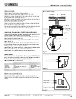
Refer to figure 6 for the wiring of Nexus models.
These units can accept an input voltage of 120 or 347 VAC:
120 VAC —
Connect the black (120 VAC) lead and white (neutral) lead
to the building utility. Insulate the red wire.
347 VAC —
Connect the red (347 VAC) lead and white (neutral) lead to
the building utility. Insulate the black wire.
Feed excess wire into the junction box.
Leave as much space as possible between the live voltage cabling and
the unsheathed low voltage data cabling.
Run the double insulation of data cables past the line cabling section and
only strip back the last 30mm of the data cable sheathing.
Automatic Diagnostics (Self-Powered Models)
There are three diagnostic indicators: one external and two internal. Unit
must be opened to gain access to internal indicators.
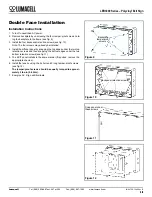
External: General alarm, “Service Required”. The LED will blink if any
alarm condition is detected (see fig. 7).
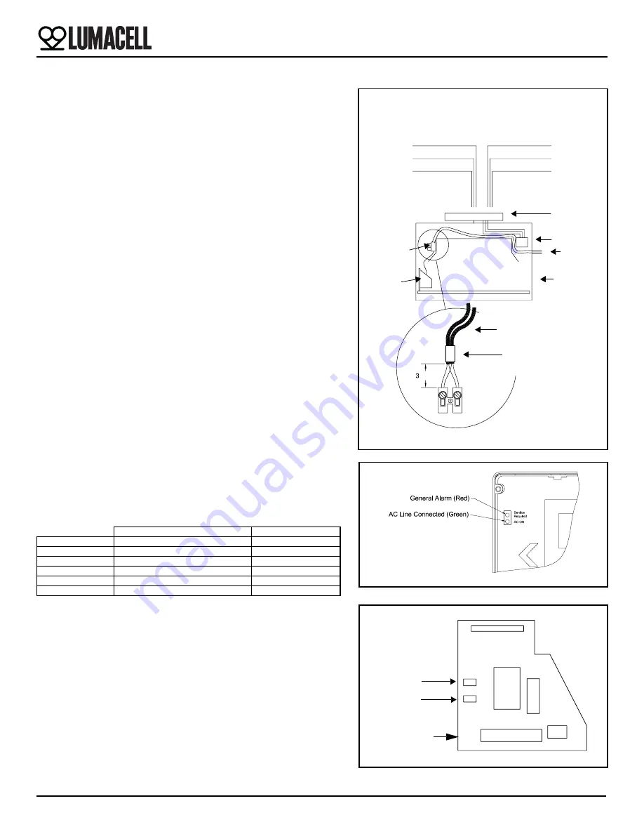
Internal: Battery Alarm & Charger Alarm. Steady ON if alarm condition
exists (See fig. 8).
Normal operation, No fault —
“Service Required” is OFF and one of
the two internal LED blinks, showing that the micro controller is active.
Faulty operation —
“Service Required” blinks.
Battery Alarm ON, Charger Alarm OFF: Check battery or replace battery.
Battery Alarm ON, Charger Alarm ON: Check LED strip.
Battery Alarm OFF, Charger Alarm ON: Check charger circuit.
Nexus models
Nexus models use two local indicators. One is a green LED for AC pilot
lamp. The other is a tricolor LED (Service) which identifies and displays
the Nexus status. The table below describes each status:
Nexus Tricolor LED —
Status table
Maintenance (All Models)
None required. If AC supply to the unit is to be disconnected for 2
months or more, the battery must be disconnected, Self-Powered Mod-
els only.
Canopy
Figure 6
LED Strip
Nexus data
Black (120)
Red (insulate)
White (neutral)
Black (insulate)
White (neutral)
Red (347)
120 VAC or 347 VAC
Sign
30 mm
Interface
Data
Tape
Nexus data cables
Nexus data
Nexus
Transformer
Nexus model wiring
terminal block
cables
Figure 7
Figure 8
Battery Alarm
Charger alarm
Diagnostic board
Uncommissioned
Commissioned
Normal
Red/Off pulsing
Green steady
Under test
N/A
Green/Off pulsing
Wink mode
Yellow-orange/(red or off) pulsing
Yellow-orange/Off pulsing
Neuron faulty
Red Steady
Red steady
Power fail
Off
Off
Battery disconnected
N/A
Off


