background image

LER3000 Series – Polyvinyl Exit Sign

4/4

Lumacell

Tel: (888) 552-6467 ext. 547 or 255

Fax: (888) 867-1565

www.lumacell.com

06/04 750.1048 Rev. B

Double Face Installation


Installation Instructions

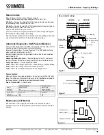
1. Turn off unswitched AC power.
2. Remove backplate by unscrewing the four tamper-proof screws hold-

ing the backplate to the frame (see fig. 9)

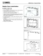
3. Install the four backpanel retention screws (see fig. 10)

Note: The four screws may already be installed.

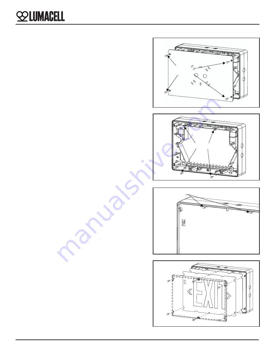
4. Install the diffuser panel by snapping the top edges under the two top 

retention screws and then snapping  the bottom edges under the two 
bottom retention screws (see fig.11).  

5. The EXIT panel installs in the same manner (if required, remove the 

appropriate chevron).

6. Install the lens by using the 4 short and 2 long tamper-proof screws 

(see fig.12).  

The tamper-proof screws should be equally torqued to approxi-
mately 5 lbs-in (0.6 N-m).

7. Energize AC.  Sign will illuminate.

Figure 9

Backplate 

screws

tamper-proof

Figure 10

Backpanel retention screws

Figure 11

Snap panel under

these screws

Figure 12

Summary of Contents for LER3000 Series

Page 1: ...of wire length c Remove proper knockouts in canopy backplate for desired mounting position For Nexus option install the liquid tight fitting provided with the unit For Ceiling mount use the k out located on side of the unit opposite side of the diagnostic display For Side mount use the k out located on top of the unit see fig 4 d Feed unswitched AC wires through large hole in canopy mount ing plat...

Page 2: ... Connect the white lead to neutral and the purple lead to AC line volt age the input is universal 110 to 347 VAC See fig 5 Optional For AC models used with DC remote power the sealed DC nipple wire assembly 2 wires will also need to be installed One end connects to the LED STRIP leads inside the enclosure and the other end to DC input inside the junction box Connect the red lead to positive and th...

Page 3: ...mal operation No fault Service Required is OFF and one of the two internal LED blinks showing that the micro controller is active Faulty operation Service Required blinks Battery Alarm ON Charger Alarm OFF Check battery or replace battery Battery Alarm ON Charger Alarm ON Check LED strip Battery Alarm OFF Charger Alarm ON Check charger circuit Nexus models Nexus models use two local indicators One...

Page 4: ...lready be installed 4 Install the diffuser panel by snapping the top edges under the two top retention screws and then snapping the bottom edges under the two bottom retention screws see fig 11 5 The EXIT panel installs in the same manner if required remove the appropriate chevron 6 Install the lens by using the 4 short and 2 long tamper proof screws see fig 12 The tamper proof screws should be eq...

Reviews: