
IN0039 - 19 May 2015
Copyright ©2015 Lumascape Lighting Industries Pty. Ltd. ABN 21 010 572 773
www.lumascape.com.au
Power supply must be isolated prior to connection
or disconnection of cables. Failure to do so will
result in damage to the luminaire components.
RGB Remote Driver
Wire Colour Designation
Red
Red +
Orange
Red -
Green
Green +
White
Green -
Blue
Blue +
Black
Blue -
RGB Integral Driver
Wire Colour Designation
AC
DC
White
AC1
+
Black
AC2
-
Orange
PWM Common
Red
PWM Red
Green
PWM Green
Blue
Blue
Single Colour Dimming
Wire Colour
Designation
AC
DC
Red or White AC1
+
Black
AC2
-
Orange
(1)
PWM + (optional)
Grey
(1)
PWM - (optional)
(1)
Do not connect if dimming is not required
Single Colour
Wire Colour
Designation
AC
DC
White
AC1 +
Black
AC2 -
Low Voltage
IMPORTANT: Please note that the PWM dimming signal polarity is
reversed with Lumascape’s LS6125 and any third party PWM controllers.
See diagram on right for details.
NOTE: If dimming is required use LS6125 PWM to 0-10 V dimming.
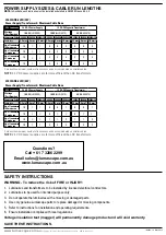
Wiring Diagrams
Exploded Diagram
LS100DC
LS22TX
LS50TX
LS100TX
LS200TX
orange (PWM _)
240 V AC
LS6122
wall plate
dimmer
0-10 V signal
OR
240 V AC
red / white +
grey (PWM +)
black _
Power supply
Options:
When dimming is NOT
required, DO NOT connect.
LS6125
Dimmer system
Supply Conduit (by others)
Connect supply conduid to niche gland
Mounting Lugs
Usa to hold niche in plae during concreting
Niche Adjustment Ring
Usa to allign luminaire in niche
Supply Cabble
Connect to a suitable power supply in
accordance with local wiring rules