ISR 12-LO/GS Manual
Controls and Installation
•
18
3.3
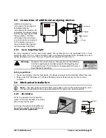
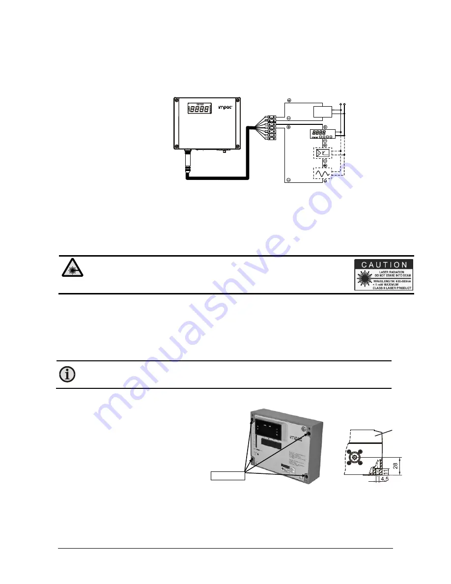
Connection of additional analyzing devices
Additional analyzing
instruments, for example a
LED digital display
instrument only needs to be
connected to a power supply
and the analog outputs from
the pyrometer. Another
instrument like a controller
or printer can be connected
to the display in series as
shown above (total load of
resistance max. 500 Ohm).
yellow
LED digital
di
l
Controller
Power supply
gree
brown
white
230 V ~
24 V
°C
Printer
3.3.1
Laser targeting light
For easy alignment to the measuring object the pyrometers can be equipped with a laser
targeting light. This is a visible red light with a wavelength between 630 and 680 nm and a
maximum power of 1 mW. The laser is classified as product of laser class II.
Warning:
To reduce the risk of injury to the eyes, do not look directly
into the targeting laser and do not point the targeting laser
into anyone's eyes. The instrument is equipped with a class II
laser that emits radiation.
Safety regulations:
•
Never look directly into the laser beam. The beam and spot can be watched safely from side.
•
Make sure that the beam will not be reflected into eyes of persons by mirrors or shiny
surfaces.
3.4
Mechanical installation
Note:
The light guide end of the fiber optic cable as well as the socket/connector and
the optical head must always be protected with the caps when not connected!
3.4.1
Pyrometer
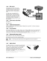
To fix the converter 4 drill holes for
screws with 4 mm diameter are visible
after removing the cover.
For fixing the optical heads different
mounting supports are available (see
2.6 Accessories (optional)
).
cover
Drill holes


