background image


ISR 12-LO/GS Manual 

General Information  

  6 

1.2.1


Electrical connection 

Follow common safety regulations for mains voltage (e.g. 230 or 115 V AC) connecting 
additional devices operating with this mains voltage (e.g. transformers). Touching mains voltage 
can be mortal. A non-expert  connection and mounting can cause serious health or material 

damages.  
 
Only qualified specialists are allowed to connect such devices to the mains voltage.  

1.3


Limit of liability and warranty 

All general information and notes for handling, maintenance, and cleaning of this instrument 
are offered according to the best of our knowledge and experience.  

LumaSense Technologies is not liable for any damages that arise from the use of any examples 

or processes mentioned in this manual or in case the content of this document should be 
incomplete or incorrect. LumaSense Technologies reserves the right to revise this document and 
to make changes from time to time in the content hereof without obligation to notify any 
person or persons of such revisions or changes. 

All instruments from LumaSense Technologies have a regionally effective warranty period. 
Please check our website at 

http://info.lumasenseinc.com/warranty

 for up-to-date warranty 

information. This warranty covers manufacturing defects and faults, which arise during 
operation, only if they are the result of defects caused by LumaSense Technologies.  

The Windows compatible software was thoroughly tested on a wide range of Windows 
operating systems and in several world languages. Nevertheless, there is always a possibility that 
a Windows or PC configuration or some other unforeseen condition exists that would cause the 
software not to run smoothly. The manufacturer assumes no responsibility or liability and will 

not guarantee the performance of the software. Liability regarding any direct or indirect 
damage caused by this software is excluded. 

The warranty is VOID if the instrument is disassembled, tampered with, altered, or otherwise 
damaged without prior written consent from LumaSense Technologies; or if considered by 

LumaSense Technologies to be abused or used in abnormal conditions. There are no user-
serviceable components in the instrument. 

1.4


Unpacking the Instrument 

Thoroughly inspect the instrument upon delivery to purchaser. Check all materials in the 
container against the enclosed packing list. LumaSense Technologies cannot be responsible for 
shortages against the packing list unless a claim is immediately filed with the carrier. Final claim 
and negotiations with the carrier must be completed by the customer. 

Save all packing materials, including the carrier’s identification codes, until you have inspected 
the pyrometer and find that there is no obvious or hidden damage. Before shipment, the 
pyrometer was examined and has been tested. If you note any damage or suspect damage, 
immediately contact the carrier and LumaSense Technologies, Inc. 

1.5


Service Request, Repair, or Support 

Contact LumaSense Technologies Technical Support in case of a malfunction or service request. 

Provide clearly stated details of the problem as well as the instrument model number and serial 
number. Upon receipt of this information, Technical Support will attempt to locate the fault 
and, if possible, solve the problem over the telephone.  

If Technical Support concludes that the instrument must be returned to LumaSense Technologies 
for repair, they will issue a Return Material Authorization (RMA) number.  

Summary of Contents for IMPAC ISR 12-LO/GS

Page 1: ...MANUAL IMPAC Pyrometer ISR 12 LO GS...

Page 2: ...nse Technologies All other trademarks are trademarks registered trademarks and or service marks of their respective holders Service Centers LumaSense Technologies Inc North America Sales Service Santa...

Page 3: ...ing 13 3 Controls and Installation 15 3 1 Electrical Installation 15 3 1 1 Pin assignment for the male socket on the bottom side of the pyrometer 15 3 1 2 Connector pin J 16 3 2 Connecting the pyromet...

Page 4: ...perating mode 1 2 M 29 4 9 Switch off limit OFF 30 4 10 Analog Output 30 4 11 Sub Range 30 4 12 Device Address 30 4 13 Baud Rate 31 4 14 Analog Test 10 mA 31 4 15 Wait time tw 31 5 Software InfraWin 3...

Page 5: ...ty note laser beam Indicates to the danger of a built in laser targeting light Text Text written in gray color explains integrated functions of the pyrometer which are not used in pouring stream mode...

Page 6: ...ondition exists that would cause the software not to run smoothly The manufacturer assumes no responsibility or liability and will not guarantee the performance of the software Liability regarding any...

Page 7: ...eight damage to instruments that are improperly packed Contact us to obtain an RMA number if Technical Support has not already assigned one Clearly indicate the assigned RMA number on the shipping pac...

Page 8: ...ISR 12 LO GS Manual General Information 8 1 8 Disposal decommissioning Inoperable instruments must be disposed of in compliance with local regulations for electronic materials...

Page 9: ...antees that even a moving pouring stream is always within the spot The pouring stream temperature of each single casting process and with that of each single casted part can be recorded automatically...

Page 10: ...ues in which must exceed the beginning of the adjusted temperature range Environment Protection Class IP 65 DIN 40 050 Ambient Temperature Converter housing 0 60 C Optical head up to 250 C Storage Tem...

Page 11: ...s 25 s extern via interface or automatically with the next measuring object hold function to freeze the actual displayed pouring stream temperature Electrical Power Supply 24 V DC 15 40 V DC or 24 V A...

Page 12: ...ISR 12 LO GS Manual Introduction 12 2 4 Dimensions Pyrometer housing Optical head cover window Lens all dimensions in mm...

Page 13: ...cal fiber 15 Mounting holes 2 6 Accessories Optional Numerous accessories guarantee easy installation of the pyrometers The following overview shows a selection of suitable accessories You can find th...

Page 14: ...ts the lens from contamination with dust and moisture It must be supplied with dry and oil free pressurized air 1 5 m h and generates an air stream shaped like a cone Displays Additionally to the buil...

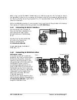
Page 15: ...cting cable has wires for power supply interface analog output external laser switch and external clear of maximum value storage via contact see section 8 Reference numbers and 12 pin connectors The c...

Page 16: ...meter To avoid wrong measurements in advance a warning signal can be set to a certain contamination level If contamination reaches this level or at a certain too low signal level a built in relays max...

Page 17: ...Bd is 7 m PC s side soldering side K A B C D J G F E H M L 1 2 3 4 5 6 7 8 9 DGND red RxD black TxD violet Pyrometer s side soldering side 3 2 2 Connecting to RS485 interface Half duplex mode A1 and A...

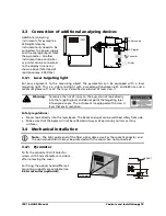
Page 18: ...f 1 mW The laser is classified as product of laser class II Warning To reduce the risk of injury to the eyes do not look directly into the targeting laser and do not point the targeting laser into any...

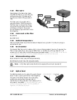
Page 19: ...housing If required the fiber can be replaced by a new original IMPAC fiber A recalibration of the pyrometer is not necessary if it is only used in ratio mode or pouring stream mode If the pyrometer i...

Page 20: ...above shows some examples for different measuring distances distance measured from front of the lens to the object see 2 4 Dimensions 3 5 2 Spot size table Optical head with line spot width Optical h...

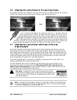
Page 21: ...size of this line varies for the different measuring distances As the alignment of the optical head is quite difficult during the pouring process it is recommended to do it before the process starts...

Page 22: ...ISR 12 LO GS Manual Controls and Installation 22 To ensure consistent document formatting this page was intentionally left blank...

Page 23: ...g of other modes only via software InfraWin see Chapter 5 Software InfraWin 4 1 Factory Settings Pouring stream mode On Start up condition 50 Pre run time 0 5 s Measuring time 0 auto Follow up time 0...

Page 24: ...activates a test current of 10 mA on the analog output independently if the instrument is adjusted to 0 to 20 mA or 4 to 20 mA This enables to test external indicators for correct scaling The readings...

Page 25: ...ring stream temperature is available Display blinking Signal strength in foundry mode is below the adjusted level 4 3 Pouring stream mode The start and end processes of the pouring disturb the tempera...

Page 26: ...process automatically and is using this period for the calculation of the temperature and shows the calculated temp on the display In both modes the temperature is displayed until the next calculated...

Page 27: ...ature by ratioing the radiation intensities of the two wavelengths This ratio technique eliminates a number of factors that degrade the accuracy of a conventional single color instrument e g measureme...

Page 28: ...tered time the storage will be deleted Extern The external clearing can be activated and used within an own software see section 7 Data format UPP or via an external contact for connection see 3 1 1 P...

Page 29: ...age stores always the highest value during the measurement value calculation Setting a value for the exposure time is smoothing this stored value so that even with interruptions in the pouring stream...

Page 30: ...ing range of the pyrometer This subrange corresponds to the analog output from describes the beginning of this measuring range to the end of the range For automatic detection of a pouring stream the b...

Page 31: ...ading of the internal indicator should correspond to the reading of the external indicator If both displays show different readings the external indicator has a wrong temperature range or input curren...

Page 32: ...ISR 12 LO GS Manual Settings Parameter Descriptions 32 To ensure consistent document formatting this page was intentionally left blank...

Page 33: ...com 5 1 Connecting the pyrometer to a PC The program InfraWin can operate up to two devices Two devices using RS485 may be operated simultaneously by the same interface if two different addresses have...

Page 34: ...ISR 12 LO GS Manual Software InfraWin 34 To ensure consistent document formatting this page was intentionally left blank...

Page 35: ...only the lens must be kept clean The lens can be cleaned with a soft cloth in combination with alcohol do not use acid solutions or dilution Also standard cloths for cleaning glasses or photo objectiv...

Page 36: ...ISR 12 LO GS Manual Maintenance 36 To ensure consistent document formatting this page was intentionally left blank...

Page 37: ...7 or 97 0 The ASCII parameter X indicates a change to be made in a parameter When used the command contains the new value Example Write Command Entry 00emXXXX CR The parameter used for the emissivity...

Page 38: ...hex 8 digit C or F XXXX beginning of temperature range YYYY end of temperature range Reading temperature sub range AAme Same as mb Setting of temperature sub range AAm1XXXXYYYY XXXX hex 4 digit begin...

Page 39: ...number AAsn Output XXXX hex 4 digit Device type software version AAve Output XXYYZZ 6 digit decimal XX 06 ISR 12 LO YY month of software version ZZ year of software version Software version in detail...

Page 40: ...ISR 12 LO GS Manual Data format UPP Universal Pyrometer Protocol 40 To ensure consistent document formatting this page was intentionally left blank...

Page 41: ...t switches 3 852 440 Protocol transducer RS485 RS232 switch Profbus DP for 1 device 3 852 460 Protocol transducer RS485 Profbus DP for 32 devices 3 852 620 Protocol converter UPP RS485 or RS232 ProfNe...

Page 42: ...ISR 12 LO GS Manual Reference Numbers 42 To ensure consistent document formatting this page was intentionally left blank...

Page 43: ...s Use mechanical construction to avoid the influence of the interfering radiation sighting tube No temperature indication at the end of the pouring stream Pouring stream is not in the spot of the pyro...

Page 44: ...ISR 12 LO GS Manual Troubleshooting 44 To ensure consistent document formatting this page was intentionally left blank...

Page 45: ...mation 5 I Installation Electrical 15 L Language 33 Laser targeting light 18 Legend 5 Lens contamination monitoring system 16 Liability 6 M Maintenance 35 Maximum value storage 16 Measuring condition...

Page 46: ...ot Sizes 20 Storage Modes 28 Sub Range 30 Support 6 Switch off limit 30 T Technical Data 10 Temperature display 24 27 Temperature sub range 25 Test current 24 Troubleshooting 43 U Unpacking the Instru...

Reviews: