background image

12 

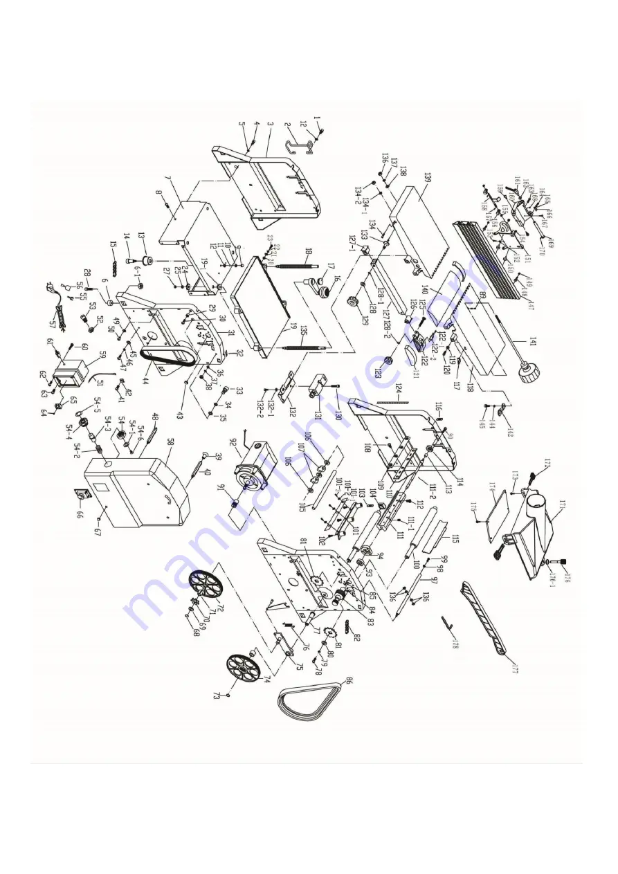
ASSEMBLY DIAGRAM 

Summary of Contents for PT254

Page 1: ...1 PT254 10 PLANER THICKNESSER ORIGINAL INSTRUCTIONS ...

Page 2: ... Diagram and List 12 15 SPECIFICATIONS Model No PT254 Motor 1500W No of Blade 2 Cutterhead rpm 8500 min 1 Weight 35 30 kg 39 34 kg with stand Technical data Planer Cutting Width max 254 mm 10 Cutting Depth max 2mm Angle fence 635x127mm Fence Angle 90 135 Working Table 920x264 mm Technical data Thicknesser Cutting Width max 254 mm 10 Cutting thickness max 6 120mm Cutting Depth max 2mm Working Table...

Page 3: ...dren 6 Don t force the tool It will do the job better and safer at the rate for when it was intended 7 Use the right tool Don t force small tools to do the job of a heavy duty tool Don t use tools for purposes not intended for example don t use circular saws to cut tree limbs or logs 8 Dress properly Don t wear loose clothing or jewelry They can be caught in moving parts Rubber gloves and non skid...

Page 4: ...d or replaced by an authorized service centre unless otherwise indicated in this instruction manual Have defective switches replaced by an authoeized service centre 21 Warning The use of any accessory or attachment other than one recommended in this instruction manual may present a risk of personal injury 22 Have your tool repaired by a qualified person This electric tool complies with the relevan...

Page 5: ...This machine must be checked periodically Defective equipment including power cable should not be used Parts that are broken missing plainly worn distorted or contaminated should be replaced immediately Should such repair or replacement become necessary it is recommended that such repairs be carried out by qualified persons This machine or any of its parts should not be altered or changed or chang...

Page 6: ...iency Refer to figure 3 Safety Switch 230V Circle Breaker Figure 3 POWER SOURCE WARNING Do not connect planer thicknesser to the power source until all assembly steps have been completed The motor is designed for operation on the voltage and frequency specified Normal loads will be handled safely on voltages not more than 10 above or below specified voltage Running the until on voltages which are ...

Page 7: ... least resistance for electrical shock OPERATION REGULATIONS ATTENTION Make sure that the switch is in off position before adjusting the cutting depth replacing or adjusting the blades Make sure the blade screws are securely tightened Assemble stand with M6 hex nut 6mm flat washer and carriage bolt Then install the machine to the stand and secure it with M8X30 hex bolt and 8mm flat washer OVERLOAD...

Page 8: ...ECTION WHEN PLANING Lift up the blade guard arm F so that the longitude holes G being exposed Pull out the key H on both sides of the dust chute E Move down the thickness table to the lowest position and insert the dust chute E F H E G Figure 6 The dust chute E is so positioned that both keys H are in line with the longitude holes G Then push both keys H into the longitude holes G refer to Fig 6 E...

Page 9: ...ver can slide to set the required stock width for jointing Push lock lever down to lock guard extrusion in position Refer to Figure 9 M L N Figure 9 PLANING The cutting depth is set by handle L at the front table plate N by means of the scale for cutting depth M Cutting depth between 0 5 and 1 5 mm 1 64 1 16 in will produce the best surface WARNING The part of the cutter head not used has to be co...

Page 10: ... Secure blade and blade clamp using three blade lock screws Do not over tighten blade lock screws first Note Check blade height at both sides of the blade Tighten blade lock screws Recheck blade adjustment and make sure blade is still level with outfeed table Repeat the procedure to replace the other blade Remove the scrap wood and release blade guard Make sure all the blade lock screws are tight ...

Page 11: ...s a clean tool improves the cutting quality This can be done by soaking the clamping devices knife supports and reversible knives for 24 hours in paraffin white spirit or commercially available resin remover Tools made of aluminum may only be deresinified with cleaning agents which do not corrode this kind of material ATTENTION Through poor conditions of the electrical MAINS shortly voltage drops ...

Page 12: ...12 ASSEMBLY DIAGRAM ...

Page 13: ...ollowing Directives Electromagnetic Compatibility Directive 2004 108 EC Machine Directive 2006 42 EC Restrictions of the use of Hazardous Substances in Electrical Equipment 2011 65 EU Waste Electrical and Electronic Equipment 2012 19 EU Standards technical specifications referred to EN 61029 1 2009 All EN 61029 2 3 2011 AfPS GS 2019 01 PAK Authorised Technical File Holder Bill Evans 01 07 2020 The...

Page 14: ...14 LUMBERJACK TOOLS UNIT C MANDERS IND EST OLD HEATH ROAD WOLVERHAMPTON WV1 2RP UNITED KINGDOM WWW LUMBERJACKTOOLS CO UK ...

Reviews: