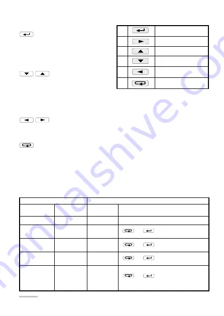
Table 1.
1
acceptance key
2
displacement key
3
increase key
4
decrease key
5
displacement key
6
resignation key
The assignment of individual keys
is as follows:
Key
It is destined to accept the introduced
value during the programmation.
It enables the change of pages in the
measuring mode.
Keys
They are destined to change the digit
value on the decimal position during the
programmation.
Keys
They allow the cursor displacement to successive decimal positions during the pro-
grammation and enable the change of display luminosity in the SETUP procedure.
Key
This key enables in anytime the resignation of carried out operations.
It cancels alarms in measuring mode.
4.2. N10A operating modes
The N10A meter has 5 operating modes represented on the table 2.
Table 2
MODE
NAME
CALLING
OUT SYMBOL
I
NPUT
OUTPUT
Measuring
default
Through entry to another mode
Time setting
t
in SETUP
procedure
, or
after the last parameter
Page
configuration
P
in SETUP
procedure
, or
after the last page
Parameter
configuration
S
Alarm
configuration
and analog
outputs
A
, or
after the last parameter
, or
after the last parameter
in SETUP
procedure
in SETUP
procedure
They enable the display of suitably minimal and maximal values in the measure-
ment mode.
Summary of Contents for N10A
Page 1: ...POWER NETWORK PARAMETER ANALYSER N10A SERVICE MANUAL...
Page 2: ......
Page 4: ......
Page 7: ...Fig 1 Overall dimensions and fitting way of the N10A meter...
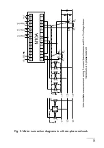
Page 10: ...10 Direct measurement in a 4 wire network Half intermediate measurement in a 4 wire network...
Page 24: ...24 Fig 6 N10A meter working modes...
Page 31: ...31...


