The A1on < A1oF setting causes the alarm inverse action, i.e. the output is swit-
ched on if the prescribed value decreases below the A1on value and the output is
switched off if the value, increases above the A1oF threshold.
Analog outputs for parameters accepting values:
-
positive and negative
(table 5), are bi-directional, i.e., for negative parameter
values, the analog output signal is also negative,
-
positive
, they are unidirectional, i.e., for positive parameter values, the analog
output signal is positive (from the range: 0...+ 5 mA).
4.2.5. Page configuration mode - P
This mode is used to select quantities displayed simultaneously on the meter, i.e.
to define user’s pages.
A list of possible quantities and their codes are inserted in the table 5.
Table 5.
Code Quantity name
Symbol Unit
Signalling Mark
00 Without quantity - display extinguished
01 Phase 1 voltage
U
1
(k)V
L1
02 Line L1 curren
I
1
(k)A
L1
03 Phase L1 active power
P
1
(M,k)W
L1
/-
04 Phase L1 reactive power
Q
1
(M,k)V
ArL1
/-
05 Phase L1 apparent power
S
1
(M,k)VA
L1
06 Phase L1 active power factor (Pf
1
= P
1
/ S
1
)
Pf
1
Pf
L1
/-
07 Phase L1 t
1
factor (t
1
= Q
1
/ P
1
)
t
1
t
L1
/-
08 Phase L2 voltage
U
2
(k)V
L2
09 Line L2 current
I
2
(k)A
L2
10 Phase L2 active power
P
2
(M,k)W
L2
/-
11 Phase L2 reactive power
Q
2
(M,k)VAr L2
/-
12 Phase L2 apparent power
S
2
(M,k)VA
L2
13 Phase L2 active power factor (Pf
2
= P
2
/S
2
)
Pf
2
Pf
L2
/-
14 Phase L2 t
2
factor (t
2
= Q
2
/P
2
)
t
2
t
L2
/-
15 Phase 3 voltage
U
3
(k)V
L3
16 Line L3 current
I
3
(k)A
L3
17 Phase L3 active power
P
3
(M,k)W
L3
/-
18 Phase L3 reactive power
Q
3
(M,k)VAr L3
/-
19 Phase L3 apparent power
S
3
(M,k)VA
L3
20 Phase L3 active power factor (Pf
3
= P
3
/S
3
)
Pf
3
Pf
L3
/-
21 Phase L3 t
3
factor (t
3
= Q
3
/P
3
)
t
3
t
L3
/-
22 Average 3-phase voltage
Us
(k)V
1,2,3
Summary of Contents for N10A
Page 1: ...POWER NETWORK PARAMETER ANALYSER N10A SERVICE MANUAL...
Page 2: ......
Page 4: ......
Page 7: ...Fig 1 Overall dimensions and fitting way of the N10A meter...
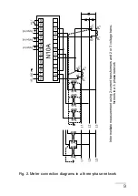
Page 10: ...10 Direct measurement in a 4 wire network Half intermediate measurement in a 4 wire network...
Page 24: ...24 Fig 6 N10A meter working modes...
Page 31: ...31...


