background image

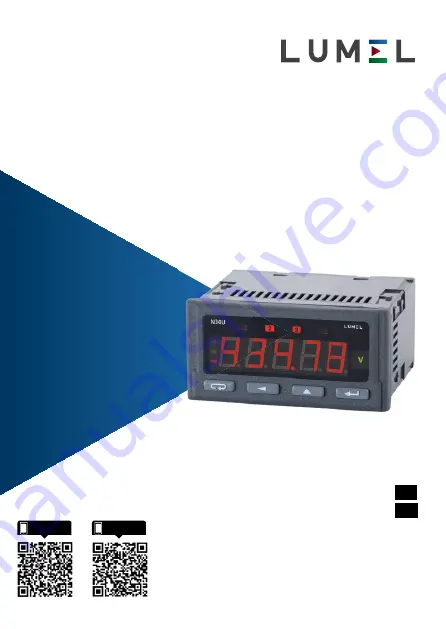
CYFROWY MIERNIK TABLICOWY

DIGITAL PANEL METER

N30U

INSTRUKCJA OBSŁUGI - SZYBKI  START

Pełna wersja instrukcji dostępna na

Full version of user’s manual available at  

www.lumel.com.pl

USER’S MANUAL - QUICK START

PL

EN

Zeskanuj mnie

Zeskanuj kod

Scan the code

Summary of Contents for N30U

Page 1: ...DIGITAL PANEL METER N30U INSTRUKCJA OBS UGI SZYBKI START Pe na wersja instrukcji dost pna na Full version of user s manual available at www lumel com pl USER S MANUAL QUICK START PL EN Zeskanuj mnie Z...

Page 2: ...e miernik jest przeznaczony do instalowania i u ywania w przemys o wych elektromagnetycznych warunkach rodowiskowych w instalacji budynku powinien by wy cznik lub wy cznik automatyczny umieszczony w p...

Page 3: ...3 pl Rys 2 Wymiary gabarytowe 2 2 Schematy pod cze zewn trznych Patrz str 24 2 1 Wyprowadzenia sygna w Patrz str 24 Rys 1 Mocowanie miernika...

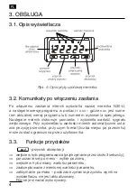
Page 4: ...tla warto sygna u wej ciowego Przy wy wietlaniu warto ci miernik automatycznie usta wia pozycj przecinka przy czym format liczba miejsc po przecinku mo e zosta ograniczona przez u ytkownika 3 3 Funkcj...

Page 5: ...zmiany parametru bezwzgl dne wyj cie z trybu programowania przytrzymanie przez oko o 3 sekundy Wci ni cie kombinacji przycisk w i przytrzymanie oko o 3 sekund powoduje kasowanie sygnalizacji alarm w O...

Page 6: ...6 pl Rys 6 Algorytm obs ugi miernika N30U W menu podgl du symbole parametr w s wy wietlane na przemian z ich warto ci Rys 6 przedstawia algorytm obs ugi miernika...

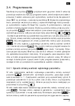
Page 7: ...j z matrycy programowania do pomiaru nale y wcisn przycisk przez oko o 1 sekund W w czas pojawi si napisu End na czas oko o 3 sekund i miernik przejdzie do wy wietlania warto ci mierzonej W przypadku...

Page 8: ...je matema tyczne 3 4 2 Zmiana warto ci zmiennoprzecinkowych Zmiana wykonywana jest w 2 etapach przej cie do nast pnego etapu nast puje po wci ni ciu przycisku 1 ustawienie warto ci z zakresu 19999 999...

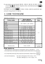
Page 9: ...cie pr dowe 24 24 mA 20 20 mA Wej cie napi ciowe 60 mV 10 63 mV 0 60 mV Aktualny czas 00 00 23 59 0 5 sekun dy dob 2 ustawienie pozycji kropki 00000 0000 0 000 00 00 000 0 0000 przycisk przesuwa krop...

Page 10: ...y 96 48 93 mm Warunki odniesienia i znamionowe warunki u ytkowania napi cie zasilania 85 253 V d c a c 40 400 Hz lub 20 40 V a c 40 400 Hz 20 60 V d c temperatura otoczenia 25 23 55o C temperatura mag...

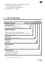
Page 11: ...cie OC RS 485 wyj cia analogowe wyj cia prze ka nikowe prze czne 2 Jednostka numer kodu jednostki wg tab 3 XX Wykonanie standardowe 00 specjalne XX Wersja j zykowa polska P angielska E inna X Pr by od...

Page 12: ...07 W 36 s 08 kW 37 h 09 MW 38 m3 10 var 39 obr 11 kvar 40 szt 12 Mvar 41 imp 13 VA 42 rps 14 kVA 43 m s 15 MVA 44 l s 16 kWh 45 obr min 17 MWh 46 rpm 18 kvarh 47 mm min 19 Mvarh 48 m min 20 kVAh 49 l...

Page 13: ...n and commissioning as well as maintenance must be carried out by qualified skilled personnel and national regulations for the prevention of accidents must be observed Before switching the meter on on...

Page 14: ...re a hole of 92 0 6 45 0 6 mm in the panel which the thickness should not exceed 6 mm The meter is adapted to be mounted in a panel The meter must be introduced from the panel front with disconnected...

Page 15: ...rements and displays the value of the input signal The meter sets up automatically the de cimal point position when displaying the value The format number of places after the decimal point can be limi...

Page 16: ...nation of the parameter change absolute exit from the programming mode holding down ca 3 seconds The pressure of the button combination and holding them down ca 3 seconds causes the reset of alarm sig...

Page 17: ...nu is carried out by means of the button In the monitoring menu parameter symbols are displayed alternately with their values The service algorithm of the meter is presented on the fig 6 Fig 6 Service...

Page 18: ...one must chose the symbol and press the button To exit from the programming matrix one must press the button during ca 1 second Then the symbol End appears for ca 3 seconds and the meter transits to t...

Page 19: ...EN 19 FUnCt Mathema tical functions Fig 7 Programming Matrix...

Page 20: ...change of the parameter value will cause the resignation of the write 4 TECHNICAL DATA Measuring Ranges Table 1 Kind of input Indication range Class Pt100 205 855 C 200 850 C 0 1 Pt500 Pt1000 400 W 0...

Page 21: ...relays switched voltageless contacts load capacity 250 V 0 5A option Analog outputs option rogrammable current 0 4 20mA load resistance 500 W programmable voltage 0 10V load resistance 500 W Output o...

Page 22: ...remaining circuits l altitude above sea level 2000 m after agreeing with the manufacturer DIGITAL PANEL METER N30U X X XX XX X X Supply 85 253 V a c 45 65 Hz or d c 1 20 40V a c 40 400 Hz 20 60 V d c...

Page 23: ...s 08 kW 37 h 09 MW 38 m3 10 var 39 obr 11 kvar 40 szt 12 Mvar 41 imp 13 VA 42 rps 14 kVA 43 m s 15 MVA 44 l s 16 kWh 45 rev min 17 MWh 46 r p m 18 kvarh 47 mm min 19 Mvarh 48 m min 20 kVAh 49 l min 2...

Page 24: ...cza miernika Obwody kolejnych grup sygna w s separowane mi dzy sob Rys 3 Opis sygna w na listwach przy czeniowych 4 1 Lead out of Signals Signals led out on the meter connectors are presented on the f...

Page 25: ...been marked by a broken line OC open collector output of npn type signaling of the measuring range overflow 0 10 V wej cie do pomiaru napi cia 10 V GND masa dla wej cia 0 10 V i wej cia 0 20 mA 0 20 m...

Page 26: ...pl EN 26 4 2 Przyk ady pod cze 4 2 Examples of Connections...

Page 27: ...r the connection of input signals in environments with a high noise level one must apply shielded wires Rys 4 Spos b pod czenia miernika Do pod czenia sygna w wej ciowych w rodowiskach o du ym po ziom...

Page 28: ...a 1 65 022 Zielona G ra Poland tel 48 68 45 75 100 fax 48 68 45 75 508 www lumel com pl Pracownia system w automatyki tel 68 45 75 228 45 75 117 Wzorcowanie tel 68 45 75 161 e mail laboratorium lumel...

Reviews: