background image


SERVICE MANUAL

SYNCHRONIZING METER

NS5

Summary of Contents for NS5

Page 1: ...SERVICE MANUAL SYNCHRONIZING METER NS5...

Page 2: ...ONFIGURATION OF THE METER 11 PARAMETERS 11 7 1 Measurement 13 7 2 Parameters 13 7 3 Relays 15 7 4 Ethernet 17 7 5 Modbus 18 7 6 Settings 19 7 7 Information 19 8 SERIAL INTERFACES 20 8 1 RS485 INTERFAC...

Page 3: ...the network and the generator frequency The synchronization point i e the moment when the frequency voltage and phase values of the generator and the network are equal is indicated by green indicator...

Page 4: ...the meter housing always turn the supply off and disconnect the measurement circuits Removal of the meter housing during the warranty period voids the warranty The synchronizing unit meets the requir...

Page 5: ...ig 3 Overall dimensions of NS5 meter 5 DESCRIPTION OF THE INSTRUMENT 5 1 Voltage inputs Voltage inputs are galvanically isolated internal transformers Un voltages phase or phase to phase are automatic...

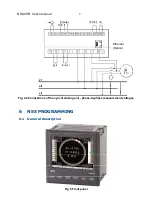
Page 6: ...NS5 09B User s manual 6 5 2 External connections diagram External connections are shown in Figures 4a 4b Fig 4a Connections of the synchronizing unit phase measurement voltages Ethernet Option...

Page 7: ...NS5 09B User s manual 7 Fig 4b Connections of the synchronizing unit phase to phase measurement voltages 6 NS5 PROGRAMMING 6 1 General description Fig 5 Front panel Ethernet Option...

Page 8: ...et lead in time Output signals relay contacts AL fault relay is activated in case of faulty external circuit connection when a fault occurs and if the measured values are outside the measuring range S...

Page 9: ...zation The spin speed and direction correspond to the difference between the network and the generator frequency Fig 7 Screen when synchronization conditions are met The values of measured parameters...

Page 10: ...phase shift range on the bar graphs screen 180 180 o 6 2 Starting operation When power is turned on the synchronizing unit displays the logo NS5 meter name version current firmware version and MAC fo...

Page 11: ...figuration of parameters of the meter Relays configuration of SYNC and AL relays Ethernet configuration of Ethernet interface parameters Modbus configuration of RS485 interface parameters Settings set...

Page 12: ...000 Gateway Address 000 000 000 000 DNS Address 008 008 008 008 MAC Address aa bb cc 00 21 01 Acquired from DHCP or entered manually when DHCP is deactivated Modbus TCP Address 001 Port 00502 Max conn...

Page 13: ...m or minimum values is done by pressing the button 7 2 Parameters In this group the parameters of the meter are set To enter the Parameters group press the button for about 3 seconds and then using th...

Page 14: ...he digit with the button or The active position is indicated by the cursor The selected characteristic or value of the parameter should be confirmed by pressing the button or canceled by pressing the...

Page 15: ...the value is too high or to the minimum value when the value is too low To configure NS5 synchronizing unit you can also use the free eCon software available at manufacturer s website 7 3 Relays Selec...

Page 16: ...relay switching delay 0 9 Pulse mode No Yes permanent switching switching pulse No 10 Width of the switching pulse ms 0 999 ms 0 11 Input signals BLK START Active Inactive Graphic illustration of BLK...

Page 17: ...SYNC relay not energized despite meeting synchronization conditions BLK signal did not change its status from 1 to 0 Fig 14 Graphic illustration of BLK and START input signals control with SYNC synch...

Page 18: ...255 255 255 255 255 0 0 1 5 Gateway Address 0 0 0 0 255 255 255 255 0 0 0 0 6 DNS Address 0 0 0 0 255 255 255 255 10 0 0 44 7 MAC Address Aa bb cc 00 21 01 8 Modbus TCP Address 1 247 1 9 Port 80 3200...

Page 19: ...ams No Yes No Fig 17 Screens of Settings group 7 7 Information Select Information group in the options and confirm by pressing the button Fig 18 Screen of Information group Table 6 No Parameter name C...

Page 20: ...r of read registers in one query 61 registers 4 byte 122 registers 2 byte implemented functions 03 04 06 16 17 03 04 registers reading 06 one register record 16 n registers record 17 device identifica...

Page 21: ...Value from the register 1B5B 7003 Check sum CRC B3 B2 B1 B0 B3 B2 B1 B0 01 03 08 41 20 00 00 42 C8 00 00 E4 6F Example 3 Readout of 2 32 bit registers of float type as a combination of 2 16 bit regist...

Page 22: ...ster 1D4D 7501 Check sum CRC B3 B2 B1 B0 B3 B2 B1 B0 01 03 08 41 20 00 00 42 C8 00 00 E4 6F Readout of single register code 06h Example 5 Record of 543 0x021F value to register 4000 0x0FA0 Request Add...

Page 23: ...nchronizing units in the NS5 XX2XXXX version are equipped with Ethernet interface that allows for connection of the synchronizing unit using RJ45 socket to a local or global network LAN or WAN Etherne...

Page 24: ...each pair foiled F FTP twisted pair cable with each pair foiled additionally cable with foil shield S FTP formerly SFTP twisted pair cable with each pair foiled additionally cable with wire mesh shie...

Page 25: ...r special preview of the current measurement values readout of the device status select the language for the Website The access to the Web server is achieved by entering the meter IP address in the we...

Page 26: ...ple http 192 168 1 30 will show the start display in the browser where the user must enter the name and password Fig 21 View of the synchronizing unit web server log window Web server user names canno...

Page 27: ...METER In NS5 meter the data are placed in 16 and 32 bit registers Process variables and parameters of the meter are located in the address space of registers in a manner dependent on the type of the v...

Page 28: ...e generator from above 0 No 1 Yes 1 4013 RW 0 200 10 Acceptable phase shift x 10 20 4014 RW 999 999 ms Lead delay time of SYNC relay switching 0 4015 RW 0 1 Switching pulse 0 permanent switching 1 swi...

Page 29: ...HCP service enabled after powering up or after selecting the menu option APPL or after entering value 1 to register 4099 the meter will automatically receive the IP address subnet mask and gateway add...

Page 30: ...d byte B3 B2 of meter MAC address format B5 B4 B3 B2 B1 B0 4423 R 0 65535 First and zero byte B1 B0 of meter MAC address format B5 B4 B3 B2 B1 B0 4424 R Reserved Device status register 1 address 4415...

Page 31: ...eserved 6024 8024 7512 R Reserved 6026 8026 7513 R Reserved 6028 8028 7514 R Reserved 6030 8030 7515 R Status register 1 6032 8032 7516 R Status register 2 6034 8034 7517 R Reserved 6036 8036 7518 R R...

Page 32: ...the upgrade process When the port is properly opened the display shows Port opened There are two ways to enter the upgrade mode remotely through the LU based on settings in eCon address mode speed COM...

Page 33: ...d quantity Measurement range Resolution Class intrinsic error Voltage Un 50 150 V 150 400 V 20 180 V 60 480 V 1920 kV tr_U 1 0 1 V 0 1 V 0 01 kV 0 2 EN 61557 12 Frequency f 40 45 65 100 Hz 0 001 Hz 0...

Page 34: ...50 Hz 7 68 kHz for 60 Hz Simultaneous sampling across all channels 128 samples per period Real time clock 20 ppm battery of RTC CR2032 Terminals Cross section 0 05 2 5 mm Clamping screws M3 Tightening...

Page 35: ...g unit Electromagnetic compatibility immunity to interference in accordance with EN 61000 6 2 noise emission acc to EN 61000 6 4 Safety requirements according to PN EN 61010 1 standard insulation betw...

Page 36: ...h M other X Acceptance tests without additional requirements 0 with quality inspection certificate 1 With calibration certificate 2 acc to customer s requirements X Un phase or phase to phase voltage...

Page 37: ...NS5 09B User s manual 37 NS5 09B...

Reviews: