14
EN
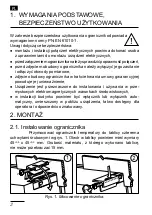
• all shields should be one-side earthed or connected to the protection
wire, the nearest possible to the temperature limiter,
• as a rule of thumb, wires transmitting different signals should be spa-
ced as far as it is possible (at least 30 cm) and should be crossed only
at the right angle of 90°.
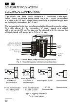
3.
STARTING OPERATION
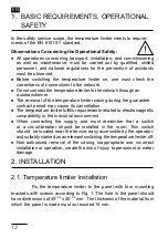
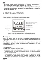
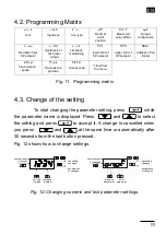
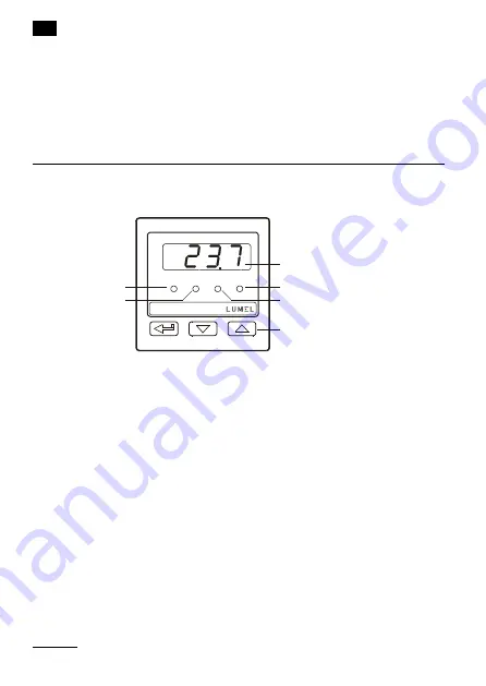
Fig. 8. View of the temperature limiter’s front panel.
Description of the temperature limiter
RL10-09 User's manual
[Wpisz tekst]
[Wpisz tekst]9
7
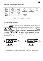
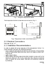
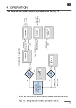
5.
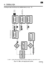
Starting operation
Description of temperature limiter
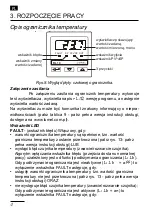
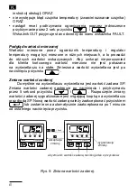
wskaźnik wyjścia
wyświetlacz pokazujący
wartość zadaną,
wartość mierzoną, menu
wskaźnik błędu
wskaźnik PV^vSP
3 przyciski
wskaźnik zmiany
wartości zadanej
FAULT
SP
PVv^SP OUT
RL10
Fig. 8: Front panel of the temperature limiter.
Powering on
When the power is turned on, the temperature limiter performs the display test, displays
rL10
, the program version, and then displays the set point.
The display may show a character message informing you of abnormalities, see table 9).
LED indicators
FAULT
-
(error indicator) Enabled when:
•
temperature limiter conditions are met, i.e. the temperature limit is
exceeded (see fig. 13) OR
•
a temperature sensor error (sensor short / open) will occur.
The algorithm to disable the error indicator (transition to normal operating
state) depends on the limitation maintaining function (
LJlt
).
When limitation maintaining is inactive (
LJlt = off
), FAULT
indicator is
disabled when:
•
temperature limiter conditions have ceased to exist, i.e. the
temperature limit is not exceeded (see fig. 13) AND
•
there is no temperature sensor error (sensor short / open); When the
limitation maintaining is active (
LJlt = on
) FAULT indicator
is deactivated when:
•
temperature limiter conditions have ceased to exist, i.e. the
temperature limit is not exceeded (see fig. 13) AND
•
there is no temperature sensor error (sensor short / open) AND
•
there has been reset of the limitation maintaining by simultaneous
pressing the
and
button for 2 sec.
The FAULT indicator takes the opposite state to the OUT indicator.
SP
-
(indicator of set point change) enabled during the change of
SP
set point.
error indicator
indicator of
change of set
point
display showing the set point,
measured value, menu
output indicator
PV^vSP indicator
3 buttons
Powering on
When the power is turned on, the temperature limiter performs the
display test, displays
rL10
, the program version, and then displays the
set point.
The display may show a character message informing you of
abnormalities, see table 9 (see full version of service manual, available
at www.lumel.com.pl).
LED indicators
FAULT
- (error indicator) Enabled when:
• temperature limiter conditions are met, i.e. the temperature limit is
exceeded (see fig. 13 - see full version of service manual, available at
www.lumel.com.pl) OR
• a temperature sensor error (sensor short / open) will occur.
The algorithm to disable the error indicator (transition to normal
operating state) depends on the limitation maintaining function (
LJlt
)


