17
EN
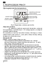
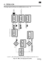
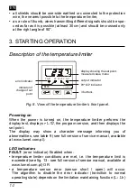
4. OPERATION
The temperature limiter service is presented on the fi g. 10
Fig. 10. Temperature limiter operation menu
RL
10
-0
9
U
se
r's
m
an
ua
l
[Wp
isz
tek
st]
[Wp
isz
tek
st]9
9
i
>
5
se
c
sse
c
FAU
LT
SP
PVv
^SP
O
U
T
FAU
LT
SP
PVv
^SP
O
U
T
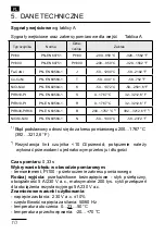
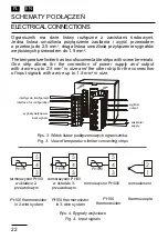
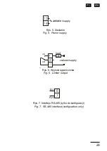
R
L1
0
Cha
ng
e
app
rov
al
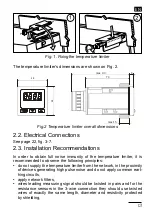
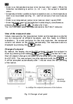
R
L1
0
si
gn
al
ing
th
e
chan
ge
to
c
hang
e
the
s
et
poi
nt
pr
es
s
one
of
the
but
to
ns
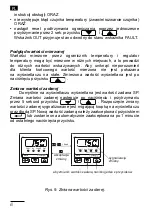
Fig
. 9
: Cha
ng
e
of
se
t p
oint
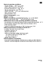
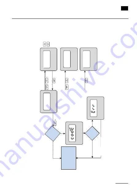
6.
Op
er
at
io
n
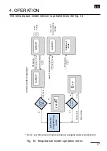
Th
e o
pe
ratio
n o
f th
e c
on
trolle
r is sh
ow
n in
Fig
ure 1
0.
Fig
. 1
0:
Te
m
pe
ra
tu
re li
m
ite
r o
pe
rati
ng
m
en
u
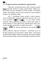
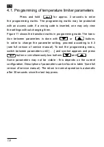
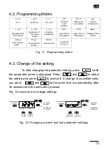
6.
1.
P
rogr
am
m
ing
te
m
per
atu
re
li
m
ite
r p
ar
amete
rs
P
ressing
an
d
ho
ldin
g
fo
r
ab
ou
t
2
se
co
nd
s
th
e
but
to
n
m
ov
es
th
e
us
er
to
th
e
prog
ram
m
ing
m
atrix
.
Th
e
prog
ramm
ing
m
at
rix
ca
n
be
p
ro
te
ct
ed
b
y
an
a
cce
ss
co
de
.
If
yo
u
en
te
r a
n in
va
lid
co
de
v
alue
, y
ou
c
an
o
nly
v
ie
w
th
e se
tting
s w
ith
out
c
hang
in
g
the
m
.
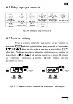
Fig
ure
11
sh
ow
s
th
e
tran
sition
m
atrix
in
prog
ram
m
ing
m
od
e.
Th
e
tra
nsition
be
tw
ee
n
pa
ra
m
et
ers
is
do
ne
w
ith
or
but
tons
.
I
n
or
de
r
to
c
ha
ng
e
the
par
am
et
er
s
et
ting
,
proce
ed
a
cc
ording
to
6
.3
. T
o e
xit t
he
p
rog
ramm
ing
men
u,
sw
itch
b
et
w
ee
n p
ara
m
et
ers un
til
[. .
.]
an
d sy
m
bo
l a
pp
ea
rs an
d p
ress
but
ton
or
s
im
ul
tane
ous
ly
tw
o
but
tons
and
.
parame
ter
pro
gram
m
in
g
m
ode
act
iv
e
acce
ss
cod
e
no
rma
l m
od
e of
op
erat
io
n
setp
oi
nt
setp
oi
nt
setp
oi
nt
m
eas
ur
ed
val
ue
va
lue
se
tting
S
ee
p.
8
O
ut
put
w
or
ki
ng
m
ode
s
ac
cept
anc
e
of
c
han
ges
res
et
o
f
limi
ta
tion
m
aint
ainin
g
P
V
pr
ev
ie
w
c
hange
lo
ck
onl
y
pr
ev
ie
w
S
P s
etti
ng
2 s
ec
.
2 s
ec
.
5
sec
.
3
s
ec
.
co
rre
ct
code
?
No
No
Ye
s
Ye
s
&
&
*
* for p.8 see full version of service manual, available at www.lumel.com.pl


