background image

25

EN

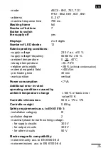
- pre-heating time 

30 min. 

- work position  

vertical

Moc pobierana  

przez 1 regulator


< 7 VA 

Storage and handling conditions

:

- storage  temperature 

-20...70

O

C

Additional error in rated  

service conditions caused  

by the change of ambient  

temperature.


100 % of the basic error  


value/10 K

Housing protection  

degree  acc. to EN 60529


IP30

Safety requirements acc. to EN 61010-1:

- installation category 

III

- pollution degree 

2

- maximal phase-to-earth work voltage:
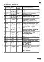
  - for supply circuits    

300 V

  - for output circuits 

300 V

  - for other circuits  

50 V

Electromagnetic compatibility

:

- noise immunity acc. to EN 61000-6-2

- noise emissions acc. to EN 61000-6-4


Table 1. Overall dimensions of the SR11 system cassette

  Cassette overall dimensions:  SR11-1XXXX  R11-3XXXX  SR11-6XXXX  SR11-8XXXX


height [mm] 

200 


197


width [mm] 

77,5 

215 

365 

465


depth [mm] 


355

 Weight of SR11 system [kg] ca. 

10 

12

Summary of Contents for SR11 Series

Page 1: ...R INJECTION MOULDS WITH HEATED CHANNELS SR11 INSTRUKCJA OBSŁUGI SZYBKI START Pełna wersja instrukcji dostępna na Full version of user s manual available at www lumel com pl USER S MANUAL QUICK START PL EN Zeskanuj mnie Zeskanuj kod Scan the code ...

Page 2: ......

Page 3: ...ch kablach równie ekranowanych Czujniki s po czone przewodami kompensacyjnymi Zestaw przy czeniowy ZP11 sk ada siê z kabla zakoñczonego wtycz kami Dla niektórych typów systemów potrzebne s dwa zestawy przy czeniowe Do pod czenia formy do zestawu przy czeniowego oferowane s opcjonalne zestawy gniazd GP11 Na tylnej œcianie systemu SR11 jest z cze przy czeniowe do pod czenia form z grzanymi kana ami ...

Page 4: ...ermopar i grza ek System SR11 czony jest z formami z grzanymi kana ami za pomoc czterech typów kabli Kable wyposa one s standardowo w 6 stykowe 380 V gniazda dla systemu SR11 1XXXX lub 16 stykowe 380 V w pozosta ych systemach Wygl d otworów monta owych oraz sposób monta u gniazd w formach pokazano na rysunkach 11 12 str 45 46 Po czenia systemu SR11 z form kablem przy czeniowym nale y wykonaæ w zal...

Page 5: ...dnie wy czyæ zasilanie g ówne a nastêpnie odkrêciæ wkrêty Podczas wk adania regulatora do obudowy systemu nale y zwróciæ uwagê aby krawêdzie p ytki regulatora znajdowa y siê w prowadnicach obudowy a nastêpnie nale y wsun æ regulator do obudowy tak aby zrówna siê z pozosta ymi i przykrêciæ œrubami Zabrania siê wk adania i wyci gania regulatorów BR11 przy w czonym g ównym wy czniku zasilania 1 3 Spo...

Page 6: ...ulsowania 1 mocy maksymalnej Rodzaj pracy regulacja automatyczna regulacja rêczna Komunikacja z komputerem interfejs RS 485 Protokó komunikacji MODBUS Szybkoœæ transmisji danych 2400 4800 9600 19200 bodów Tryb transmisji ASCII 8N1 7E1 7O1 RTU 8N2 8E1 8O1 8N1 Adres 0 247 Maksymalny czas odpowiedzi 700 ms Znamionowe warunki u ytkowania napiêcie zasilania systemu 2 8 strefowego 3 x 230 V 400 V a c 10...

Page 7: ...ji III stopieñ zanieczyszczenia 2 maksymalne napiêcie pracy wzglêdem ziemi dla obwodów zasilania 300 V dla obwodu wyjœciowego 300 V dla pozosta ych obwodów 50 V Kompatybilnoœæ elektromagnetyczna odpornoœæ na zak ócenia elektromagnetyczne wg normy PN EN 61000 6 2 emisja zak óceñ elektromagnetycznych wg normy PN EN 61000 6 4 Tabela 1 Wymiary gabarytowe kaset systemu SR11 Wymiary gabarytowe kasety SR...

Page 8: ... 12 minut Na górnym wyœwietlaczu wyœwietlana jest temperatura mierzona a na dolnym wartoœæ natê enia pr du grza ki w amperach Po miêkkim starcie regulator wykonuje algorytm automatycznego doboru parametrów PID Faza ta jest sygnalizowana impulsowym œwieceniem wskaŸnika Po wykonaniu identyfikacji obiektu regulator automatycznie oblicza wartoœci parametrów algorytmu PID i Fuzzy Logic i przechodzi do ...

Page 9: ...e maksymalnego pr du up ywu uszkodzenie w obwodzie czujnika pomiarowego alarm wzglêdny dolny lub górny od odchy ki WskaŸniki stanów alarmowych WskaŸniki informuj ce o wyœwietlanych parametrach Wyœwietlacz wartoœci mierzonej Wyœwietlacz wartoœci zadanej mocy wyjœciowej lub natê enia pr du WskaŸniki trybu pracy regulatora Przyciski do ustawiania parametrów i wyboru trybów pracy Wy cznik zasilania Uc...

Page 10: ...tlanej O C moc wyjœciowa w na dolnym wyœwietlaczu natê enie pr du p yn cego przez odbiornik na dolnym wyœwietlaczu Trzecia grupa to wskaŸniki w kolorze zielonym informuj ce o trybie pracy regulatora tryb pracy rêcznej tryb miêkki start miganie sygnalizuje fazê autoadaptacji tryb obni onej temperatury miganie sygnalizuje za czenie trybu wejœciem binarnym tryb pracy automatycznej ...

Page 11: ... wartoœci SPL zmniejsze nie wartoœci mocy na wyjœciu przejœcie do nastêpnego para metru lub zmniej szenie wartoœci parametru prze czenie wyœwietlania kolejnych parametrów na dolnym wyœwietlaczu rozpoczêcie nastawy parametru lub zaakceptowanie nastawionej wartoœci wartoœæ zadana moc wyjœciowa natê enie pr du odbiornika moc wyjœciowa natê enie pr du od biornika wejœcie w tryb programowania wyjœcie z...

Page 12: ...ub poprzedniego parametru w kolejnoœci wg tabeli 3 Aby zmieniæ wartoœæ parametru nale y nacisn æ przycisk wartoœæ parametru pulsuje naciskaj c przyciski i nastawiæ dan wartoœæ parametru ponownie nacisn æ przycisk co oznacza zaakceptowanie nowej wartoœci parametru lub przycisk aby zrezygnowaæ ze zmiany Je eli przez 45 sekund aden przycisk nie by naciœniêty regulator wy chodzi z trybu programowania ...

Page 13: ...an a temperatur powy ej której nale y sygnalizowaæ alarm 6 adl 2 20 O C 10 O C ró nica pomiêdzy wartoœci 36 68 O F zadan a temperatur powy ej której nale y sygnalizowaæ alarm 7 p 1 999 4 zakres proporcjonalnoœci w zakresu pomiarowego 8 ti 0 999 sek 120 sta a czasowa ca kowania 9 td 0 999 sek 20 sta a czasowa ró niczkowania 10 seC 0 999 0 kod bezpieczeñstwa 11 adr 0 247 0 adres regulatora w sieci 1...

Page 14: ...cie ustawione na sygna z pracy rêcznej lub na œredni moc poprzedzaj c uszkodzenie off wyjœcie wy czone 18 bus off off format danych podczas komunikacji an1 z systemem nadrzêdnym ae1 off komunikacja wy czona ao1 an1 tryb ASCII 8 bitów danych rn2 bez bitu parzystoœci 1 bit stopu re1 ae1 tryb ASCII 7 bitów danych ro1 bit parzystoœci 1 bit stopu ao1 tryb ASCII 7 bitów danych bit nieparzystoœci 1 bit s...

Page 15: ...wietlaczu pojawi siê nazwa parametru seC a na dolnym pulsuj ca wartoœæ 000 Przyciskami i nale y podaæ w aœciwy kod i nacisn æ W przypadku b êdnego kodu pojawi siê komunikat err Po naciœniêciu dowolnego przycisku komunikat ten znika a regulator wraca do przegl dania parametrów Aby zmieniæ kod bezpieczeñstwa nale y najpierw podaæ jego aktualn wartoœæ a gdy pojawi siê napis sen wprowadziæ now wartoœæ...

Page 16: ... up ywnoœci 0 25 0 mA Dynamika PID sterowanie rozmyte Fuzzy Logic Zakres proporcjonalnoœci 1 999 zakresu pomiarowego Sta a czasowa ca kowania 0 999 sek Sta a czasowa ró niczkowania 0 999 sek Miêkki start stopniowy narost temperatury do wartoœci spr Autoadaptacja po miêkkim starcie gdy aua jest w czone Zaniki zasilania powrót do trybu przed zaniku zasilania Wykrywanie i sygnalizacja uszkodzeñ przek...

Page 17: ...rza 85 bez kondensacji pary wodnej zewnêtrzne pole magnetyczne 400 A m czas wstêpnego nagrzewania 30 min po o enie pracy pionowe Moc pobierana 7 VA B d dodatkowy w znamionowych warunkach u ytkowania spowodowany zmian temperatury otoczenia 100 wartoœci b êdu podstawowego 10 K Wymiary 50 6 x 174 x 175 Masa 0 65 kg Wymagania bezpieczeñstwa wg PN EN 61010 1 kategoria instalacji III stopieñ zanieczyszc...

Page 18: ... 6 Szerokoœæ obudowy 465 mm iloœæ regulatorów 7 8 8 Iloœæ regulatorów 1 regulator 1 2 regulatory 2 3 regulatory 3 4 regulatorów 4 5 regulatorów 5 6 regulatorów 6 7 regulatorów 7 8 regulatorów 8 Interfejs RS 485 Bez interfejsu 0 Z interfejsem 1 Z cza do formy Wspólne z cza do termoelementów i grza ek 1 Rozdzielone z cza do termoelementów i grza ek1 2 Dodatkowe wymagania2 bez dodatkowych wymagañ 0 z...

Page 19: ...ia standardowe 0 z atestem Kontroli Technicznej 1 wg uzgodnieñ z odbiorc 2 X Tabela 5 Kod wykonañ zestawu przy czeniowego ZP11 Przyk ad Kod SR11 6 5 0 1 0 oznacza system do form z grzanymi kana ami w obudowie o szerokoœci 365 mm z 5 regulatorami bez interfejsu RS 485 ze wspólnym kablem dla termoelementów i grza ek bez dodatkowych wymagañ Przyk ad Kod ZP11 1 2 0 oznacza zestaw przy czeniowy systemu...

Page 20: ...o ZP11 3XX i ZP11 5XX3 3 1 Dla kabli ze wspólnymi przewodami grza ek i termopar do jednego kabla po trzebne jest jedno gniazdo mêskie 2 Dla kabli z rozdzielonymi przewodami grza ek i termopar do jednego kabla grza ek potrzebne jest jedno gniazdo mêskie 3 Dla kabli z rozdzielonymi przewodami grza ek i termopar do jednego kabla termopar potrzebne jest jedno gniazdo eñskie Przyk ad Kod GP11 3 oznacza...

Page 21: ...ected to the earth potential Signalling wires of SR11 6XX2X and SR11 8XX2X systems are led in separate cables also shielded Sensors are connected by compensating wires To connect the mould to the connection set GP11 socket sets are op tionally offered On the rear side of the SR11 system there are the connection cable to the injection mould and the DB 25 signalling connector to connect the RS 485 i...

Page 22: ...heater wires Moulds with heated channels are connected with the SR11 system by means of four types of cables Cables are equipped in standard with 6 plug 380 V connectors for the SR11 11X1X system or with 16 plug 380 V connectors for other systems The view of mounting holes and the mounting way of sockets in moulds are shown on fig 11 and 12 pages 45 46 Connections of the SR11 system with the mould...

Page 23: ... supply on successive heating zones are turned on by push buttons situated on the controller frontal plate After turning controllers on one must set the required temperature value in the way described in the user s manual of BR11 controllers In order to pull out the BR11 controller from the system housing one must absolutely turn the main supply off and next undo fixing nuts and take the controlle...

Page 24: ... Pulse repetition period automatically selected Impulse resolution 1 of the max power Kind of work automatic control manual control Communication with the computer RS 485 interface Communication protocol MODBUS Baud rate 2400 4800 9600 19200 bits Transmission mode ASCII 8N1 7E1 7O1 RTU 8N2 8E1 8O1 8N1 Adress 0 247 Maximal response time 700 ms Rated service conditions supply voltage of the 2 8 zone...

Page 25: ...30 Safety requirements acc to EN 61010 1 installation category III pollution degree 2 maximal phase to earth work voltage for supply circuits 300 V for output circuits 300 V for other circuits 50 V Electromagnetic compatibility noise immunity acc to EN 61000 6 2 noise emissions acc to EN 61000 6 4 Table 1 Overall dimensions of the SR11 system cassette Cassette overall dimensions SR11 1XXXX R11 3XX...

Page 26: ...minutes The measured temperature is displayed on the upper display and the current intensity of heaters in amperes on the lower display After the soft start the controller performs the algorythm of the automa tic selection of PID parameters This phase is signalled by the impulse lighting of the indicator After the object identifying the controller calculates automatically parameter values of the P...

Page 27: ...max leakage current damage in the circuit of the measuring sensor relative lower or upper alarm from the deviation Indicators of alarm states Indicators informing about displayed parameters Display of measured value Display of set point value output power or current intensity Indicators of vontroller operating mode Push buttons to set parameters and the operating mode selection Supply swith Holder...

Page 28: ...tput lower in on the lower display current flowing through the load on the lower display The third group of indicators in green colour informs about the controller operating mode manual operating mode soft start mode the flickering signals the autotuning phase mode of decreased temperature the flickering signals the turn of the mode on by the logic input automatic operating mode ...

Page 29: ...se of the power value on the output transition to the next parameter or decrease of the parameter value Switching of the successive parameter display on the lower display beginning of the parameter setting change or accep tation of the set value set point output power intensity of the load current output power intensity of the load current entry in the programming mode exit from the programming mo...

Page 30: ...ameter in the sequence acc to the table 3 To measure the parameter value one must press the push button the parameter value is flickering pressing and push buttons set the required parameter value press the push button again what means the acceptation of the new parameter value or the push button to resign from the change If during 45 sec none of the push buttons is not been pressed the controller...

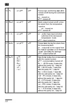
Page 31: ...F and the temperature above which one must signal the alarm 6 adl 2 20 O C 10 O C Difference between the set value 36 68 O F and the temperature belowwhich one must signal the alarm 7 p 1 999 4 Proportional band in of the measuring range 8 ti 0 999 sek 120 Integration time constant 9 td 0 999 sek 20 Differentiation time constant 10 seC 0 999 0 Safety code 11 adr 0 247 0 Controller address in the n...

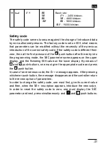
Page 32: ... on the signal from the manual operation or on the mean power preceding the damage off output turned off 18 bus off off Data format during the communication an1 with the master system ae1 off communication turned off ao1 an1 ASCII mode 8 data bits rn2 without the parity bit 1 stop bit re1 ae1 ASCII mode 7 data bits ro1 with the parity bit 1 stop bit ao1 ASCII mode 7 data bits with the odd parity b...

Page 33: ...ing 000 value on the lower display By means of and push buttons one must give the appropriate code and press the push button In case of an erroneous code the err message appears After pressing whichever push button the message disappears and the controller return to the review option of parameters In order to change the safety code one must first give its current value and then when the sen inscri...

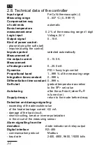
Page 34: ... PID fuzzy logic control Proportional band 1 999 of the measuring range Integration time constant 0 999 s Differentiation time constant 0 999 s Soft start gradual temperature accretion to the spr set value Autotuning after the soft start when aua is turned on Supply decays return to the mode before decay Detection and damage signaling exceeding of the admissible value of the heater leakage current...

Page 35: ...out condensation external magnetic field 400 A m pre heating time 30 min work position vertical Power consumption 7 VA Additional error in rated operating conditions caused by ambient temperature change 100 of basic error value 10 K Controller dimensions 50 6 x 174 x 175 Controller weight 0 65 kg Safety requirements acc to EN 61010 1 installation category III pollution degree 2 maximal phase to ea...

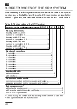
Page 36: ...5 mm number of controllers 7 8 8 Number of controllers 1 controller 1 2 controllers 2 3 controllers 3 4 controllers 4 5 controllers 5 6 controllers 6 7 controllers 7 8 controllers 8 Interface RS 485 without interface 0 with interface 1 Connectors for the mould common connectors for thermocouples and heaters 1 separate connectors for thermocouples and heaters1 2 Extra requirements 2 without extra r...

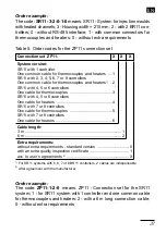
Page 37: ...th an extra quality inspection certificate 1 acc to user s agreements 2 X Table 5 Order codes for the ZP11 connection set Order example The code SR11 3 2 0 1 0 means SR11 System for injection moulds with heated channels 3 Housing width 215 mm 2 with 2 BR11 con trollers 0 without RS 485 interface 1 with common connectors for thermocouples and heaters 0 without extra requirements Order example The c...

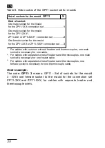
Page 38: ... For cables with common wires of heaters and thermocouples one male socket is necessary for one cable 2 For cables with separated wires of heaters and thermocouples one male socket is necessary for one heater cable 3 For cables with separated wires of heaters and thermocouples one female socket is necessary for one thermocouple cable Order example The code GP11 3 means GP11 Set of sockets for the ...

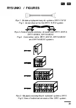
Page 39: ...iowy do systemów SR11 3XX1X SR11 6XXXX SR11 8XXXX Fig 1 Connection set to the SR11 11X1X system Fig 2 Connection set to SR11 3XX1X SR11 6XXXX and SR11 8XXXX systems Fig 3 View of individual versions of the SR11 system Rys 3 Wygl d poszczególnych wykonañ systemu SR11 RYSUNKI FIGURES ...

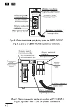
Page 40: ...pl EN 40 Rys 4 Rozmieszczenie przy czy systemu SR11 1XX1X Fig 4 Lay out of SR11 1XXXX system connectors Rys 5 Rozmieszczenie przy czy systemu SR11 3XX1X Fig 5 Lay out of SR11 3XX1X system connectors ...

Page 41: ...PL EN 41 Fig 6 Lay out of SR11 6XX1X system connectors Fig 7 Lay out of SR11 8XX1X system connectors Rys 6 Rozmieszczenie przy czy systemu SR11 6XX1X Rys 7 Rozmieszczenie przy czy systemu SR11 8XX1X ...

Page 42: ...pl EN 42 Rys 8 Kompletacja systemu SR11 z zestawami przy czeniowymi ZP11 Fig 8 Completion of the SR11 system with ZP11 connector sets ...

Page 43: ...PL EN 43 Rys 9 Uproszczony schemat po czeñ wewnêtrznych systemu SR11 8XX1X Fig 9 Simplified diagram of internal SR11 8XX1X system connections ...

Page 44: ...pl EN 44 Rys 10 Uproszczony schemat po czeñ wewnêtrznych systemu SR11 8XX2X Fig 10 Simplified diagram of internal SR11 8XX2X system connections ...

Page 45: ...X zawieraj cych 1 regulator BR11 z lewej lub SR11 3XX1X zawieraj cych 2 lub 3 regulatory BR11 z prawej Fig 11 Mounting way of the plug in socket on the injection mould for the SR11 11X1 system including 1 BR11 controller on the left or SR11 3XX1X including 2 or 3 BR11controllers on the right ...

Page 46: ...R11 6XXXX zawieraj cych 4 5 lub 6 regulatorów BR11 i dla SR11 8XXXX zawieraj cego 7 lub 8 regulatorów BR11 Fig 12 Mounting way of the plug in socket on the injection mould for the SR11 6XXXX system including 4 5 or 6 BR11 controllers or for SR11 8XXXX including 7 or 8 BR11 controllers ...

Page 47: ...onnections Rys 13 Schemat po czeñ zewnêtrznych systemu SR11 11X1X Fig 14 Connection diagram of external SR11 33X1X system con nections including 3 blocks of BR11 controllers Rys 14 Schemat po czeñ zewnêtrznych systemu SR11 33X1X zawieraj cego 3 bloki regulatorów BR11 ...

Page 48: ...N 48 Fig 15 Connection diagram of external SR11 66X1X system connections including 6 blocks of BR11 controllers Rys 15 Schemat po czeñ zewnêtrznych systemu SR11 66X1X zawieraj cego 6 bloków regulatorów BR11 ...

Page 49: ...9 Rys 16 Schemat po czeñ zewnêtrznych systemu SR11 66X2X zawieraj cego 6 bloków regulatorów BR11 Fig 16 Connection diagram of external SR11 66X2X system connections including up to 8 blocks of BR11 controllers ...

Page 50: ...N 50 Rys 17 Schemat po czeñ zewnêtrznych systemu SR11 88X1X zawieraj cego 8 bloków regulatorów BR11 Fig 17 Connection diagram of external SR11 88X1X system connections including 8 blocks of BR11 controllers ...

Page 51: ...N 51 Rys 18 Schemat po czeñ zewnêtrznych systemu SR11 88X2X zawieraj cego 8 bloków regulatorów BR11 Fig 18 Connection diagram of external SR11 88X2X system connections including 8 blocks of BR11 controllers ...

Page 52: ... 2 System SR11 32X1X 8 7 4 6 5 3 2 1 16 15 12 14 13 11 10 9 PE PE TC2 GRZ2 TC1 GRZ1 BR11 F o A C o P S S BR11 F o A C o P S S BR11 F o A C o P S S SR11 33X1X 1 2 3 System SR11 33X1X 8 7 4 6 5 3 2 1 16 15 12 14 13 11 10 9 PE TC2 GRZ2 PE TC3 GRZ3 TC1 GRZ1 Tabela A Table A ...

Page 53: ... P S S SR11 66XXX 1 2 3 4 5 6 System SR11 66X2X TC6 8 7 4 6 5 3 2 1 16 15 12 14 13 11 10 9 PE PE GRZ5 GRZ4 GRZ3 8 7 4 6 5 3 2 1 16 15 12 14 13 11 10 9 PE PE TC5 TC4 TC3 GRZ6 GRZ2 GRZ1 TC2 TC1 System SR11 66X1X PE 8 7 4 6 5 3 2 1 16 15 12 14 13 11 10 9 PE 8 7 4 6 5 3 2 1 16 15 12 14 13 11 10 9 PE PE G1 G2 TC5 GRZ5 TC6 GRZ6 TC2 GRZ2 TC1 GRZ1 TC3 GRZ3 TC4 GRZ4 G1 G2 BR11 BR11 BR11 F o A C o P S S BR1...

Page 54: ...TC1 GRZ1 TC2 GRZ2 TC3 GRZ3 G1 G2 BR11 F o A C o P S S BR11 F o A C o P S S BR11 F o A C o P S S BR11 F o A C o P S S BR11 F o A C o P S S BR11 F o A C o P S S BR11 F o A C o P S S BR11 F o A C o P S S SR11 88XXX 1 2 3 4 5 6 7 8 System SR11 88X2X GRZ5 GRZ4 GRZ3 8 7 4 6 5 3 2 1 16 15 12 14 13 11 10 9 PE PE GRZ8 GRZ7 GRZ6 GRZ2 GRZ1 TC8 TC7 TC6 8 7 4 6 5 3 2 1 16 15 12 14 13 11 10 9 PE PE TC5 TC4 TC3 ...

Page 55: ......

Page 56: ...howska 1 65 022 Zielona Góra Poland tel 48 68 45 75 100 fax 48 68 45 75 508 www lumel com pl Pracownia systemów automatyki tel 68 45 75 228 45 75 117 Wzorcowanie tel 68 45 75 161 e mail laboratorium lumel com pl Export department tel 48 68 45 75 139 45 75 233 45 75 321 45 75 386 45 75 353 fax 48 68 32 54 091 e mail export lumel com pl Calibration Attestation tel 68 45 75 161 e mail laboratorium lu...

Reviews: