OmniCure
®
Series 1500
Quick Start Guide
SIDE 2
Caution eye damage may result from directly viewing ultraviolet light – protective eye shielding and clothing must be used at all times
Lumen Dynamics Group Inc.
Tel: 1-905-821-2600
2260 Argentia Rd.
Toll Free: 1-800-668-8752
Mississauga, Ont. L5N 6H7
Fax: 1-905-821-2055
www.ldgi-uv.com
Installing the Lamp Module
The OmniCure
®
S1500 curing system is available configured in two different
versions. One version is for standard curing and one version is for surface
curing. The appropriate type of lamp must be installed depending on which
configuration your S1500 is set.
1. Be sure the AC power cord is disconnected from the unit.
2. Remove the screw from the lamp access side panel using the tool
provided and remove the panel from the unit cover.
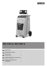
3. Carefully remove the lamp module from its container, holding only the
ceramic component and glass rim
4.
As illustrated below, position the lamp facing towards the front of the unit
with the power leads facing towards you.
Caution:
Do not touch the bulb’s glass envelope or the inside surface of
the reflector. Skin oils can cause the lamp module to fail prematurely.
5. Make sure the middle of the lamp is in position to fit into the spring
clamp. Slide the lamp until it snaps into the spring clamp. The leading
edge of the reflector should fit snugly into the lamp holder recess.
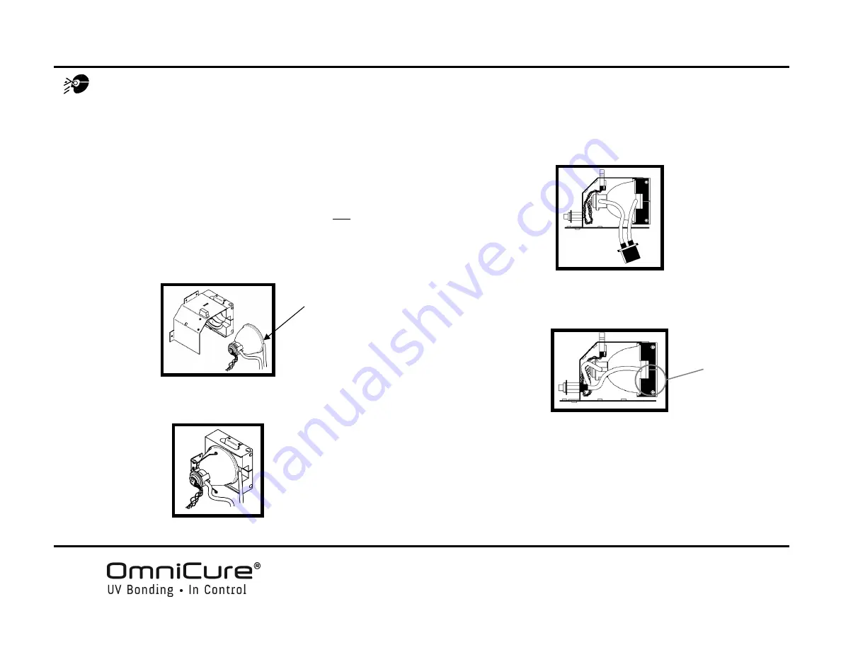
6. Locate the 4-pin Intelli-Lamp sensor connector at the rear of the lamp module
and connect it to its mate located on the top of the lamp-housing wall.
Tip:
the Intelli-lamp connector will only attach in the correct orientation. If you
are having difficulty attaching the connector, try rotating it by 180º.
7. Locate the Power connector with two leads and connect it to its mate located
on the bottom of the lamp-housing wall.
Tip:
the Lamp Power connector will only attach in the correct orientation. If
you are having difficulty inserting the connector, try rotating it by 180º.
8. It is very important to ensure that the lamp anode cooling fin (bar) and
lamp power lead, at the front of the lamp are centered within the lamp
holder cutout. Rotate the lamp as required.
9. Replace the lamp housing side panel and tighten the fastening screw.
Note 1:
if the lamp housing panel is not secured completely, the lamp will not
strike and the “
bulb
” message will display when power is turned on to the unit.
Note 2:
if the wrong type of lamp has been installed in your unit, the message
“
E1
” will appear on the LED display.
R
IM
*C
ENTER
LAMP POWER
LEAD AS
SHOWN
*