AB217 LUXEON HR30 Application Brief 20160504 ©2016 Lumileds Holding B.V. All rights reserved.
7
3. Thermal Management
The overall thermal performance of LUXEON emitter is affected by the following factors:
a. PCB layout, construction and material as described in section 2.4.
b. LEDs spacing (e.g. close packing).
c. Thermal interface materials (TIM) property if assembled PCB is mounted onto a heatsink.
d. Orientation of the LED strips, module or heat sink (e.g. vertical or horizontal mounting and LED facing upwards
or downwards).
e. Presence of air flow or still air.
f. Presence of nearby heat source (e.g. inefficient LED driver generates heat during operation).
4. Thermal Measurement Guidelines
The typical thermal resistance Rθ
j-case
between the junction and the solder pads of the LUXEON emitter is provided in the
datasheet. With this information, the junction temperature T
j
can be determined according to the following equation:
T
j
= T
case
+ Rθ
j-case
• P
electrical
In this equation T
case
is the temperature at the bottom of the solder pads of the LUXEON emitter and P
electrical
is the electrical
power going into the emitter. In typical applications it may be difficult, though, to measure the temperature T
case
directly.
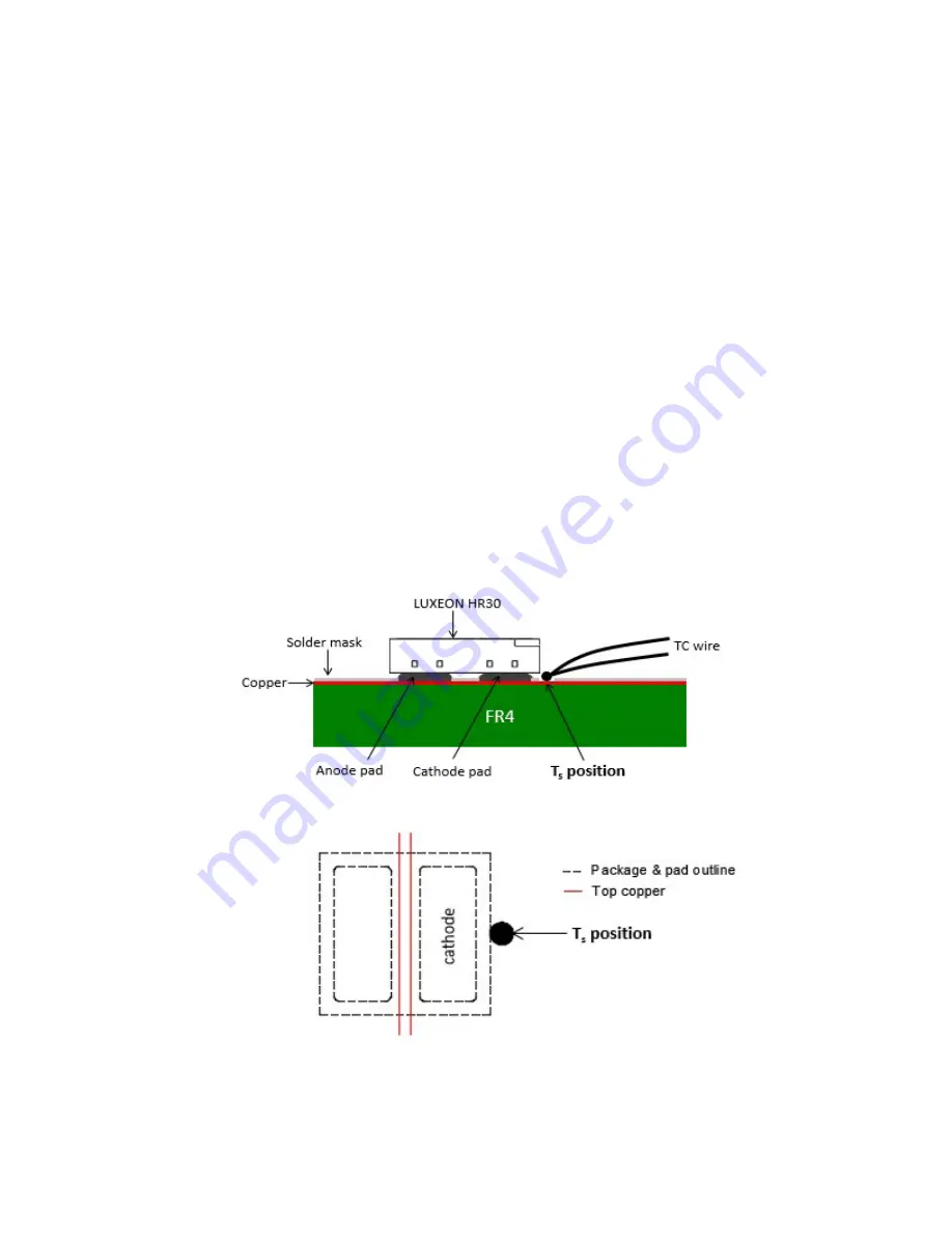
Therefore, a practical way to determine the junction temperature of the LUXEON emitter is by measuring the temperature
T
s
of a predetermined sensor pad on the PCB with a thermocouple (TC).
Figure 7. The recommended temperature measurement point T
s
is located on the cathode copper layer of the PCB, closest to
the package. The top picture shows the side view. Bottom picture shows the top view of the T
s
location.

