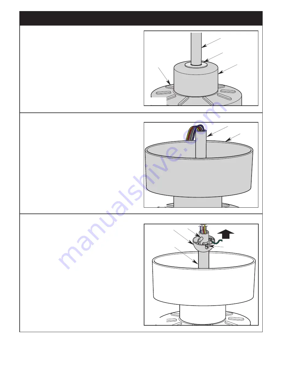
DOWNROD
RUBBER
GROMMET
MOTOR
COUPLER
COVER
MOTOR
HOUSING
Figure 10
3.10
Make sure the Rubber Grommet is properly installed in
the Motor Coupler Cover .
Slide the Motor Coupler Cover on the Downrod until it
rests on the Motor Housing (Figure 10) .
9
luminancebrands.com
Please contact 1-800-777-4440 for further assistance
ETL Model No.: CF345 & CF355
CEILING
COVER
DOWNROD
Figure 11
3.11
Place the Ceiling Cover over the Downrod (Figure 11) .
Be sure that the Ceiling Cover and the Motor Coupler
Cover are both oriented correctly (Figure 11) .
3. Ceiling Fan Assembly
(Continued)
PIN
4.5"
DOWNROD
HANGER BALL
PHILLIPS
SET SCREW
Figure 12
3.12
Route the Wires through the Hanger Ball (Figure 12) .
Reinstall the Hanger Ball on the Downrod as follows:
Position the Pin through the Two Holes in the Downrod
and align the Hanger Ball so the Pin is captured in the
Groove in the top of the Hanger Ball (Figure 12) .
Pull the Hanger Ball up tight against the Pin and
securely tighten the Phillips Set Screw in the Hanger
Ball (Figure 12) .
NOTE: A loose Set Screw could create Fan wobble.


