background image

11

luminancebrands.com

Please contact 1-800-777-4440 for further assistance

U.L. Model No.: SW93/SW95/SW96

Luminance Brands Ceiling Fan Product Limited Warranty

What The Limited Warranty Covers:

This limited warranty is offered by Luminance Brands (“Luminance Brands” or “our” or “we” or “us”) to the original purchaser (“you” or “your”) of a consumer or industrial 

Luminance Brands ceiling fan product including its motor and the other components, and accessories of a consumer or industrial Luminance Brands ceiling fan product 

sold separately (“Luminance Brands Ceiling Fan Product(s)”) against defects in workmanship and materials, subject to the exclusions described below.
What The Limited Warranty Period Of Coverage Is:

All limited warranty periods herein begin on the date of original Luminance Brands Ceiling Fan Product purchased by You. 

This limited warranty covers the Luminance Brands consumer Ceiling Fan Product motor for the lifetime of the original purchaser’s ownership when operated in accordance 

with Your Luminance Brands Ceiling Fan Product Owner’s Manual or other instructions provided by Luminance Brands to You with the Luminance Brands consumer 

Ceiling Fan Product. 

This limited warranty covers the Luminance Brands Industrial Ceiling Fan Product motor for five years from the date of purchase of Your Luminance Brands Industrial 

Ceiling Fan Product (when operated in accordance with Your Luminance Brands Ceiling Fan Product Owner’s Manual or other instructions provided by Luminance Brands 

to You with the Luminance Brands Industrial Ceiling Fan Product).

This limited warranty covers the Luminance Brands Ceiling Fan Product LED drivers and LED arrays component or accessory LED drivers and LED arrays for a period of 

five (5) years. All other components of the Luminance Brands Ceiling Fan Product certified as ENERGY STAR® including motor electronics are covered by this limited 

warranty for a period of three (3) years. All other components and accessories of the Luminance Brands Ceiling Fan Product including motor electronics are covered by 

this limited warranty for a period of one (1) year. 
No Other Express or Implied Warranty Applies:

THE LIMITED WARRANTIES PROVIDED ABOVE ARE THE SOLE AND EXCLUSIVE WARRANTIES PROVIDED BY LUMINANCE BRANDS TO YOU FOR YOUR Luminance 

Brands Ceiling Fan Product, AND ARE IN LIEU OF ALL OTHER WARRANTIES, WRITTEN OR ORAL, EXPRESS OR IMPLIED, WHETHER ARISING BY OPERATION OF LAW 

OR OTHERWISE, WHETHER OR NOT THE PURPOSE HAS BEEN DISCLOSED AND WHETHER OR NOT THE Luminance Brands Ceiling Fan Product HAS BEEN SPECIFI-

CALLY DESIGNED OR MANUFACTURED FOR YOUR USE OR PURPOSE. LUMINANCE BRANDS HEREBY DISCLAIMS ANY AND ALL IMPLIED WARRANTIES, INCLUDING 

WITHOUT LIMITATION, IMPLIED WARRANTIES OF MERCHANTABILITY OR FITNESS FOR A PARTICULAR PURPOSE. 
How You Can Receive Warranty Service:

You must be the original purchaser and have proof of Your purchase of Luminance Brands Ceiling Fan Product from an authorized Luminance Brands Dealer to obtain Your 

remedy under this limited warranty. You can return Your Luminance Brands Ceiling Fan Product to an authorized Luminance Brands Dealer, or You can call Luminance 

Brands Customer Service at 1-800-777-4440 to obtain a return authorization and service identification tag.  In order for Us to confirm that Your Luminance Brands Ceiling 

Fan Product is still under warranty, please retain Your receipt or other proof of purchase and have that information readily available when returning Your Luminance Brands 

Ceiling Fan Product to Your place of purchase, or upon calling Luminance Brands Customer Service. If You call Luminance Brands Customer Service, prior to Your call, 

please be prepared to provide all model numbers shown on Your Luminance Brands Ceiling Fan Product. Once We have processed your return authorization request, We 

will provide You with a postage paid return label which should be affixed to the Luminance Brands Ceiling Fan Product package You ship. The return label will be sent to 

the mailing address You provide to Us by phone.
What We Will Do To Correct Problems:

If the defect is covered by this limited warranty, Luminance Brands will repair or replace the applicable Luminance Brands Ceiling Fan Product at no charge to You. If 

repair of the Luminance Brands Ceiling Fan Product is not practical or possible within a reasonable time and no replacement Luminance Brands Ceiling Fan Product can 

be provided, Luminance Brands will refund You the actual purchase price of Your Luminance Brands Ceiling Fan Product. We will ship the repaired or the replacement 

Luminance Brands Ceiling Fan Product to You at no charge, but You are responsible for all costs of removal and reinstallation of Your Luminance Brands Ceiling Fan Product.
What Is Not Covered under the Limited Warranty:

This limited warranty does not extend to and expressly excludes:

•  The glass globes and light bulbs of Your Luminance Brands Ceiling Fan Product,

•  Any costs or fees associated with the labor, including electrician’s fees, required to install, remove, repair or replace a fan or any fan components or accessories.

•  Loss or damage to the Luminance Brands Ceiling Fan Product motor or any Luminance Brands Ceiling Fan Product component or Luminance Brands Ceiling Fan 

Product accessory caused by normal wear and tear, rather than due to defects in materials or workmanship,

•  Loss or damage resulting from conditions beyond our reasonable control, including without limitation, unforeseeable operating environmental conditions, repairs not 

made at Our factory or authorized service center, use of parts or accessories not provided to You as part of this warranty by Our factory or authorized service center, 

mishandling, unreasonable use, misuse, abuse, modifications or other damage caused by You or a third party to your Luminance Brands Ceiling Fan Product while not in 

Our possession,

•  Loss or damage resulting from improper installation, or other failure to comply with instructions in Your Owner’s Manual including but not limited to Luminance 

Brands Ceiling Fan Products installed in unintended industrial or residential applications.

•  Luminance Brands Ceiling Fan Product purchases from unauthorized Luminance Brands Dealers.
This limited warranty is deemed null and void upon the occurrence of either of the following events:

•  You as the original purchaser cease to own the Luminance Brands Ceiling Fan Product, or

•  The Luminance Brands Ceiling Fan Product is moved from its original point of installation.

This limited warranty is only valid within the 50 United States, the District of Columbia, and Canada. No other written or oral warranties apply, and no employee, agent, 

dealer or other person is authorized to give any warranties on behalf of Us.
Limitation of Liability:

REPAIR, REPLACEMENT OR A REFUND ARE THE EXCLUSIVE REMEDIES AVAILABLE TO YOU UNDER THIS LIMITED WARRANTY. TO THE EXTENT PERMITTED BY LAW 

IN NO EVENT SHALL LUMINANCE BRANDS OR ANY LUMINANCE BRANDS AUTHORIZED DEALER BE LIABLE FOR ANY INCIDENTAL, SPECIAL, INDIRECT, OR CONSE-

QUENTIAL DAMAGES, INCLUDING ANY ECONOMIC LOSS, WHETHER RESULTING FROM NONPERFORMANCE, USE, MISUSE OR INABILITY TO USE THE Luminance 

Brands Ceiling Fan Product OR FOR THE NEGLIGENCE OF LUMINANCE BRANDS OR A LUMINANCE BRANDS AUTHORIZED DEALER. LUMINANCE BRANDS SHALL NOT 

BE LIABLE FOR DAMAGES CAUSED BY DELAY IN PERFORMANCE AND IN NO EVENT, REGARDLESS OF THE FORM OF THE CLAIM OR CAUSE OF ACTION (WHETHER 

BASED IN CONTRACT, INFRINGEMENT, NEGLIGENCE, STRICT LIABILITY, OTHER TORT OR OTHERWISE), SHALL LUMINANCE BRANDS’ OR ANY LUMINANCE BRANDS 

AUTHORIZED AGENT’S LIABILITY TO YOU OR ANY INDIVIDUAL USING THE Luminance Brands Ceiling Fan Product EXCEED THE PRICE PAID BY THE ORIGINAL OWNER 

FOR THE Luminance Brands Ceiling Fan Product. The term “consequential damages” shall include, but not be limited to, loss of anticipated profits, business interruption, 

loss of use or revenue, cost of capital or loss or damage to property or equipment. 
Dispute Resolution:

In the event of any dispute INCLUDING, BUT NOT LIMITED TO, BREACH OF CONTRACT, BREACH OF WARRANTY, CLAIMS BASED IN TORT, NEGLIGENCE, PRODUCT 

LIABILITY, FRAUD, MARKETING, STATE OR FEDERAL REGULATIONS, ANY CLAIMS REGARDING THE ENFORCEABILITY OF THIS LIMITED WARRANTY, AND THE 

WAIVER OF CLASS ACTION TRIALS between You and Luminance Brands, either party may choose to resolve the dispute by binding arbitration, as described below, 

instead of in court. THIS MEANS IF EITHER YOU OR LUMINANCE BRANDS CHOOSE BINDING ARBITRATION, NEITHER PARTY SHALL HAVE THE RIGHT TO LITIGATE 

SUCH CLAIM IN COURT OR HAVE A JURY TRIAL. DISCOVERY AND APPEAL RIGHTS ARE LIMITED IN BINDING ARBITRATION. You and Luminance Brands agree that 

the proper venue if Arbitration is not so chosen by You or Luminance Brands of all actions arising in connection herewith shall be only in the state of Ohio and the parties 

agree to such jurisdiction. 

CLASS ACTION WAIVER: BINDING ARBITRATION MUST BE ON AN INDIVIDUAL BASIS. THIS MEANS NEITHER YOU NOR LUMINANCE BRANDS MAY JOIN OR CONSOL-

IDATE CLAIMS IN ARBITRATION BY OR AGAINST OTHERS, OR LITIGATE IN COURT OR ARBITRATE ANY CLAIMS AS A REPRESENTATIVE OR MEMBER OF A CLASS 

OR IN A PRIVATE ATTORNEY GENERAL CAPACITY.

ADMINISTRATION OF ARBITRATION: The binding arbitration must be administered by the American Arbitration Association (“AAA”) in accordance with its Commercial 

Arbitration Rules and/or Supplementary Procedures for Consumer-Related Disputes (including proceedings to mitigate costs of travel). This binding arbitration is governed 

by the Federal Arbitration Act (“FAA” (9 USC §1, et. seq.) and will govern the interpretation and enforcement. The binding arbitration shall be held at a location determined 

by AAA or at such other location as mutually agreed In addition to the terms stated above, the following will apply to the binding arbitration: (1) the arbitrator, and not 

any federal, state, or local court or agency, will have exclusive authority to resolve any dispute relating to the interpretation applicability, enforceability or formation of this 

agreement including any claim that all or any part of this agreement is void or voidable; (2) the arbitrator shall apply Ohio law consistent with the FAA.
How State and Provincial Law Relates To The Warranty:

Some states and provinces do not allow the exclusion or limitation of incidental or consequential damages so the above exclusion or limitation may not apply to You. This 

limited warranty gives you specific legal rights, and You may also have other rights which vary from state to state or province to province.

Summary of Contents for SW93

Page 1: ...t have enough electrical wiring knowledge or experience have your Fan Control installed by a licensed electrician Electrical installation should be made or approved by a licensed electrician 5 Use of this control with some ceiling fans could result in fire shock and serious personal injury Use this speed control only with ceiling fans that are suitable for use with solid state controls 6 This prod...

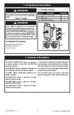
Page 2: ...r replacement parts 1 800 777 4440 WARNING 1 1 Package Contents 1 Unpacking Instructions Part Description Quantity A Wall Control Switch 1 B Knobs 2 C Wire Connectors 3 Tools Needed for Assembly This product is designed to use only those parts supplied with this product and or any ac cessories designated specifically for use with this product by Luminance Brands Substitution of parts or accessorie...

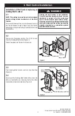
Page 3: ...ceiling fan must be set at the highest speed setting before installation of the Wall Control Disconnect Electrical Power to the Branch Circuit at the Circuit Breaker Panel or Main Fuse Box before attempting to install the Ceiling Fan Wall Control into the Wall Box 3 2 Remove the Faceplate and the Two 6 32 Screws from the Existing Wall Switch Figure 1 Retain Faceplate and Screws for future use SCRE...

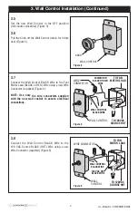
Page 4: ...trical connections TO 120VAC SOURCE HOT FAN MOTOR BLACK OR RED WIRE WALL CONTROL BLACK WIRE TO FAN MOTOR LOAD WALL CONTROL WIRE CONNECTOR 4 U L Model No SW93 SW95 SW96 3 Wall Control Installation Continued 3 5 Set the new Wall Control in the OFF position full counter clockwise Figure 3 3 6 Pull the Knob off the Wall Control retain for future use Figure 3 Figure 3 WALL CONTROL KNOB 3 8 Connect the ...

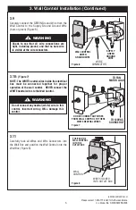
Page 5: ...f the wall control NEVER connect the WHITE neutral wires to the Wall Control 3 Wall Control Installation Continued 3 9 Securely connect the GREEN Ground Wire from the Wall Control to the Supply Ground Ground Wire bare or green Figure 6 3 11 Carefully tuck all Wires and Wire Connectors into the Wall Box and position the Wall Control onto the Wall Box Figure 8 WIRE CONNECTOR SUPPLY GREEN GROUND WIRE...

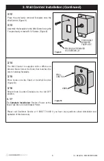
Page 6: ...ED 6 32 SCREWS 2 Figure 9 3 14 The Wall Control is supplied with a White and Almond Knob Select the Knob that matches the color of existing Faceplate 3 15 Press Knob onto the Shaft of the Wall Control Figure 10 3 16 Rotate Knob Counter Clockwise to the full OFF position 3 17 To Complete Installation Restore Power at the Main Fuse Box or Circuit Breaker Panel KNOB WALL CONTROL Please call Customer ...

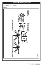
Page 7: ...urther assistance U L Model No SW93 SW95 SW96 4 Wall Control Wiring Diagrams 4 1 SW93 Dual Fan Wall Control Figure 11 Figure 11 TO NEUTRAL TO FAN MOTOR LOAD TO 120VAC SOURCE HOT SW93 DUAL FAN WALL CONTROL MOTOR LOAD BLACK BLACK BLACK or RED BLACK GREEN GREEN ...

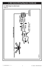
Page 8: ...95 SW96 4 Wall Control Wiring Diagrams Continued 4 2 SW95 Single Fan Wall Control Figure 12 Figure 12 TO NEUTRAL TO FAN MOTOR LOAD TO 120VAC SOURCE HOT SW95 SINGLE FAN WALL CONTROL BLACK BLACK BLACK or RED BLACK GREEN GREEN ...

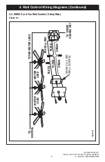
Page 9: ... U L Model No SW93 SW95 SW96 4 Wall Control Wiring Diagrams Continued 4 3 SW96 3 or 4 Fan Wall Control 5 Amp Max Figure 13 Figure 13 TO NEUTRAL TO FAN MOTOR LOAD TO 120VAC SOURCE HOT SW96 3 or 4 FAN WALL CONTROL BLACK BLACK BLACK or RED BLACK GREEN GREEN MOTOR LOAD MOTOR LOAD ...

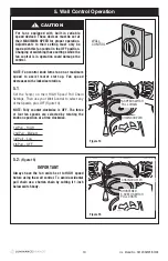
Page 10: ...ipped with built in variable speed devices These devices must be set at their MAXIMUM SPEED for proper operation Adjustments to their setting must only be made with this fan control in the OFF position Changing or switching these settings while the fan control is in operation could damage the control CAUTION 1st Pull HIGH 2nd Pull Medium 3rd Pull Low 4th Pull OFF CHAIN COUPLER 3 SPEED SWITCH PULL ...

Page 11: ... Luminance Brands Ceiling Fan Product component or Luminance Brands Ceiling Fan Product accessory caused by normal wear and tear rather than due to defects in materials or workmanship Loss or damage resulting from conditions beyond our reasonable control including without limitation unforeseeable operating environmental conditions repairs not made at Our factory or authorized service center use of...

Page 12: ...sion 03052021 Printed in China 03 2021 1 800 777 4440 www luminancebrands com Retain this manual for future use Questions problems missing parts Before returning to the store Call Customer Service 370 Falls Commerce Pkwy Cuyahoga Falls OH 44224 ...

Page 13: ...ia en materia de cableado eléctrico haga que un electricista con licencia instale su control de pared Cualquier trabajo eléctrico no descrito en este manual deberá se realizado por un electricista con licencia 5 La utilización de este control con algunos ventiladores de techo podría causar un incendio descargas eléctricas y lesiones corporales graves Utilice este control de velocidad solamente con...

Page 14: ... 4440 ADVERTENCIA 1 1 CONTENIDO DE HERRAJES 1 Instrucciones de desempaquetado Pieza Descripción Cantidad A Interruptor del control de pared 1 B Botón giratorio 2 C Conector de cables 3 Herramientas necesarias para el ensamblaje Este producto está diseñado para utilizarse solamente con aquellos ventiladores de techo que estén designados específicamente para utilizarse con este producto por Luminanc...

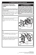
Page 15: ...talar el control de pared Desconecte la alimentación eléctrica al circuito derivado en el panel de cortacircuitos o la caja de fusibles principal antes de intentar instalar el ventilador de techo en la caja de pared 3 2 Retire la placa frontal y los dos tornillos 6 32 del interruptor de pared existente Figura 1 Retenga la placa frontal y los tornillos para uso futuro SCREWS WALL BOX WALL SWITCH FA...

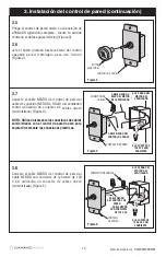
Page 16: ...trol de pared nuevo en la posición de APAGADO girándolo completa mente en sentido contrario al de las agujas del reloj Figura 3 3 6 Jale el botón giratorio hasta retirarlo del control apagada pared reténgalo para uso futuro Figura 3 Figura 3 WALL CONTROL KNOB 3 8 Conecte el cable NEGRO del control de pared al cable NEGRO con corriente de la fuente de 120 V CA utilizando un conector de cables nuevo...

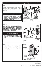
Page 17: ...red al cable de conexión a tierra de la alimentación pelado o verde Figura 6 3 11 Introduzca cuidadosamente por completo todos los cables y conectores de cables en la caja de tomacorriente y posicione el control de pared sobre dicha caja Figura 8 WIRE CONNECTOR SUPPLY GREEN GROUND WIRE WALL CONTROL GREEN GROUND WIRE Figura 6 TO 120VAC SOURCE HOT TO FAN MOTOR LOAD DO NOT CONNECT ANY WIRES FROM WALL...

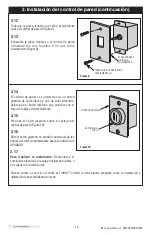
Page 18: ...con el color de la placa frontal existente 3 15 Presione el botón giratorio sobre el vástago del control de pared Figura 10 3 16 Rote el botón giratorio en sentido contrario al de las agujas del reloj completamente hasta la posición de APAGADO 3 17 Para finalizar la instalación Restablezca el suministro eléctrico en la caja principal de fusibles o en el panel de cortacircuitos KNOB WALL CONTROL Sí...

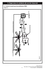
Page 19: ...trol de pared para dos ventiladores SW93 Figura 11 Figura 11 TO NEUTRAL TO FAN MOTOR LOAD TO 120VAC SOURCE HOT SW93 DUAL FAN WALL CONTROL MOTOR LOAD BLACK BLACK BLACK or RED BLACK GREEN GREEN A NEUTRO CARGA DEL MOTOR NEGRO VERDE CONTROL DE PARED PARA DOS VENTILADORES SW93 VERDE A LA FUENTE DE 120 V CA CON CORRIENTE NEGRO NEGRO o ROJO A LA CARGA DEL MOTOR DEL VENTILADOR NEGRO ...

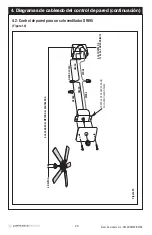
Page 20: ...ventilador SW95 Figura 12 Figura 12 TO NEUTRAL TO FAN MOTOR LOAD TO 120VAC SOURCE HOT SW95 SINGLE FAN WALL CONTROL BLACK BLACK BLACK or RED BLACK GREEN GREEN A NEUTRO A LA CARGA DEL MOTOR DEL VENTILADOR NEGRO NEGRO VERDE CONTROL DE PARED PARA UN SOLO VENTILADOR SW95 VERDE A LA FUENTE DE 120 V CA CON CORRIENTE NEGRO NEGRO o ROJO ...

Page 21: ...para 3 o 4 ventiladores SW96 5 A máx Figura 13 Figura 13 TO NEUTRAL TO FAN MOTOR LOAD TO 120VAC SOURCE HOT SW96 3 or 4 FAN WALL CONTROL BLACK BLACK BLACK or RED BLACK GREEN GREEN MOTOR LOAD MOTOR LOAD CARGA DEL MOTOR CARGA DEL MOTOR A NEUTRO A LA CARGA DEL MOTOR DEL VENTILADOR NEGRO NEGRO VERDE CONTROL DE PARED PARA 3 o 4 VENTILADORES SW96 VERDE A LA FUENTE DE 120 V CA CON CORRIENTE NEGRO NEGRO o ...

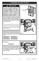
Page 22: ...sitivos de velocidad variable incorpo rados Estos dispositivos se deben ajustar a su VELOCIDAD MÁXIMA para que funcionen correctamente Los ajustes de la posición de velocidad deben ser realizados sola mente con este control de ventilador en la posición de APAGADO Si se cambian o conmutan estos ajustes mientras el control de ventilador esté en funcionamiento se podría dañar el control PRECAUCIÓN 1e...

Page 23: ...ponente del Producto de Ventilador de Techo Luminance Brands o accesorio del Producto de Ventilador de Techo Luminance Brands por causa del desgaste por el uso normal en lugar de por causa de defectos de materiales o de fabricación Pérdida o daño que resulte de situaciones que estén más allá de nuestro control razonable incluyendo sin limitación condiciones ambientales operativas imprevisibles rep...

Page 24: ...03052021 Impreso en China 03 2021 1 800 777 4440 www luminancebrands com Retenga este manual para uso futuro Preguntas problemas piezas faltantes Antes de devolver el producto a la tienda llamar a servicio al cliente 370 Falls Commerce Pkwy Cuyahoga Falls OH 44224 ...

Page 25: ... du câblage électrique faites installer votre commande murale par un élec tricien professionnel Tout travail électrique qui n est pas décrit dans ce mode d emploi doit être réalisé par un électricien professionnel 5 L utilisation de cette commande avec certains ven tilateurs de plafond pourrait causer un incendie un choc électrique et des blessures corporelles graves N utilisez cette commande de v...

Page 26: ...s d interurbain 1 800 777 4440 1 1 PETIT MATÉRIEL DE FIXATION 1 Instructions pour le déballage Pièce Description Quantité A Interrupteur Commande murale 1 B Bouton 2 C Capuchon de connexio 3 Outils nécessaires à l assemblage Ce produit est conçu pour être utilisé uniquement avec les pièces qui sont fournies avec ce produit et ou tous accessoires spécifiquement désignés comme pouvant être utilisés ...

Page 27: ...n de la commande murale Déconnectez l alimentation électrique du circuit de dérivation au niveau du panneau de disjoncteurs ou de la boîte à fusibles principale avant d essayer d installer la commande murale du ventilateur de plafond dans la boîte murale 3 2 Retirez le cache et les deux vis 6 32 de la commande murale existante Figure 1 Conservez le cache et les vis afin de pouvoir les réutiliser u...

Page 28: ...a position d arrêt en la faisant tourner à fond dans le sens contraire des aiguilles d une montre Figure 3 3 6 Tirez sur le bouton de la commande murale pour le détacher conservez le afin de pouvoir le réutiliser ultérieurement Figure 3 Figure 3 WALL CONTROL KNOB 3 8 Connectez le fil NOIR de la commande murale avec le fil NOIR de la source d alimentation secteur 120 V c a en utilisant un nouveau c...

Page 29: ... fil de mise à la terre d alimentation nu ou vert Figure 6 3 11 Faites entrer tous les fils et capuchons de connexion dans le boîtier de prises de courant en prenant de grandes précautions et positionnez la commande murale dans le boîtier de prises de courant Figure 8 WIRE CONNECTOR SUPPLY GREEN GROUND WIRE WALL CONTROL GREEN GROUND WIRE Figure 6 TO 120VAC SOURCE HOT TO FAN MOTOR LOAD DO NOT CONNE...

Page 30: ... à la couleur du cache existante 3 15 Appuyez sur le bouton pour le pousser contre la tige de la commande murale Figure 10 3 16 Faites tourner le bouton dans le sens contraire des aiguilles d une montre pour mettre la commande totalement dans la position hors tension 3 17 Achèvement de l installation remettez sous tension depuis le coffret à fusibles principal ou le disjoncteur KNOB WALL CONTROL V...

Page 31: ...ur deux ventilateurs SW93 Figure 11 Figure 11 TO NEUTRAL TO FAN MOTOR LOAD TO 120VAC SOURCE HOT SW93 DUAL FAN WALL CONTROL MOTOR LOAD BLACK BLACK BLACK or RED BLACK GREEN GREEN VERS LE NEUTRE CHARGE DU MOTEUR NOIR NOIR VERT COMMANDE MURALE POUR DEUX VENTILATEURS SW93 VERT VERS LA SOURCE D ALIMENTATION SECTEUR 120 V c a NOIR NOIR ou ROUGE VERS LA CHARGE DU MOTEUR DU VENTILATEUR ...

Page 32: ... Figure 12 Figure 12 TO NEUTRAL TO FAN MOTOR LOAD TO 120VAC SOURCE HOT SW95 SINGLE FAN WALL CONTROL BLACK BLACK BLACK or RED BLACK GREEN GREEN VERS LE NEUTRE VERS LA CHARGE DU MOTEUR DU VENTILATEUR NOIR NOIR VERT COMMANDE MURALE POUR VENTILATEUR UNIQUE SW95 VERT VERS LA SOURCE D ALIMENTATION SECTEUR 120 V c a NOIR NOIR ou ROUGE ...

Page 33: ...entilateurs 5 A max Figure 13 Figure 13 TO NEUTRAL TO FAN MOTOR LOAD TO 120VAC SOURCE HOT SW96 3 or 4 FAN WALL CONTROL BLACK BLACK BLACK or RED BLACK GREEN GREEN MOTOR LOAD MOTOR LOAD CHARGE DU MOTEUR CHARGE DU MOTEUR VERS LE NEUTRE VERS LA CHARGE DU MOTEUR DU VENTILATEUR NOIR NOIR VERT COMMANDE MURALE POUR 3 OU 4 VENTILATEURS SW96 VERT VERS LA SOURCE D ALIMENTATION SECTEUR 120 V c a NOIR NOIR ou ...

Page 34: ... dispositifs doivent être réglés sur leur VITESSE MAXIMUM afin de rendre possible un fonctionnement correct Tout réglage d un tel paramètre ne peut être effectué que si la commande de ce ventilateur est en position d arrêt La modifi cation ou la commutation de ces paramètres alors que la commande du ventilateur serait en position de fonctionnement pourrait endom mager cette commande CHAIN COUPLER ...

Page 35: ... Produit pour un ventilateur de plafond Luminance Brands ou un accessoire d un Ventilateur ou Produit pour un ventilateur de plafond Luminance Brands causés par l usure normale plutôt que par des défauts de fabrication ou de matériel Les pertes et dommages résultant de conditions au delà de notre contrôle raisonnable y compris sans toutefois s y limiter les conditions environnementales de fonction...

Page 36: ... Chine 03 2021 1 800 777 4440 www luminancebrands com Conservez ce mode d emploi pour toute utilisation future Questions problèmes pièces manquantes Avant de retourner un produit au magasin téléphoner le service à la clientèle 370 Falls Commerce Pkwy Cuyahoga Falls OH 44224 ...

Reviews: