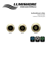
Surface Mount
e
-lites
Page 3
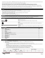
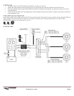
2.0 INSTALLATION
2.1 Materials:
Drill and bits for cable and pilot hole screws:
Cable
PILOT
3M 4200 sealant (or equivalent)
Philips type screwdriver
On/Off switch (breaker panel)
Waterproof connectors or soldering iron and heat shrink tubing
Rag(s) for cleanup
7/16 (10.5mm)
9/64 (3.5mm)
2.2
Mounting:
1.
Select a suitable flat surface that is accessible from behind and ensure the cable can be run without a problem.
IMPORTANT:
The ‘LUMISHORE’ logo on the light must be positioned at the top when securing to the hull.
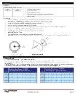
2.
Drill the pilot and the power cable holes using the drill bits mentioned in Section 2.1.
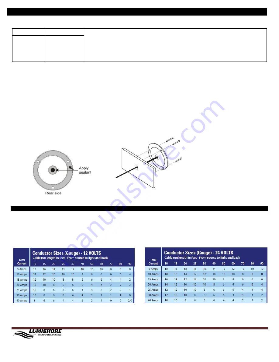
3.
Apply a single bead of sealant around the cable entry and screw holes.
4.
Apply a continuous thick bead of sealant approximately 0.4” (10mm) from the edge of the light and around the cable. Refer to image below.
5.
Push the power cable through the hole and align the light with the pilot hole screws.
6.
Attach the light using the 3 stainless steel screws by hand tightening with a screwdriver.
IMPORTANT:
Do Not Over Tighten
7.
Use a damp cloth to wipe off excess sealant that was squeezed out around the light.
IMPORTANT:
For underwater installation: Refer to the directions on the sealant to make sure it has fully cured before launching the boat in to the water.
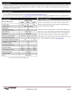
3.1 Selecting cable gauge
Proper wire cable size must be considered when installing the lights.
Use the tables below to compute the gauge of the cable needed, noting current draw of each light at 12VDC or 24VDC.
Keep in mind cable lengths referenced in the Conductor Size tables are from the source to the lights and back to the source (twice the actual distance).
Two calculations:
1. Calculate the total current draw of all lights connected to the terminal strip. Then use the table to calculate the cable size needed from the source to the junction box.
2. If the cable supplied on the light is not long enough. Use the calculation table to compute the gauge of the cable needed for each light.
Figure 1: SEALANT AREAS
Figure 2: LIGHT MOUNTING
3.0 ELECTRICAL