45-0101 - Rev 2.0
3
www.Lumishore.com
Lumishore UK Unit 2, Technium 1, Kings Road, Swansea, SA1 8PH, UK | +44(0)208 144 1694 | Info@Lumishore.com
4. Remove the clear fuse panel and insert the fuses (supplied):
12V
DC
7.5A
24
V
DC
4A
Once the fuses are in place replace the fuse panel.
5. Select a position for the SUPRA i-Connect Hub Switch. Mount the
switch and run the cable to the hub. Connect the switch connector to
the hub. The switch cable can be extended up to 50m. To extend, cut
the switch cable, and connect in a 18 AWG, 3 core cable of the desired
length. Take care to ensure that the correct conductors are connected
together.
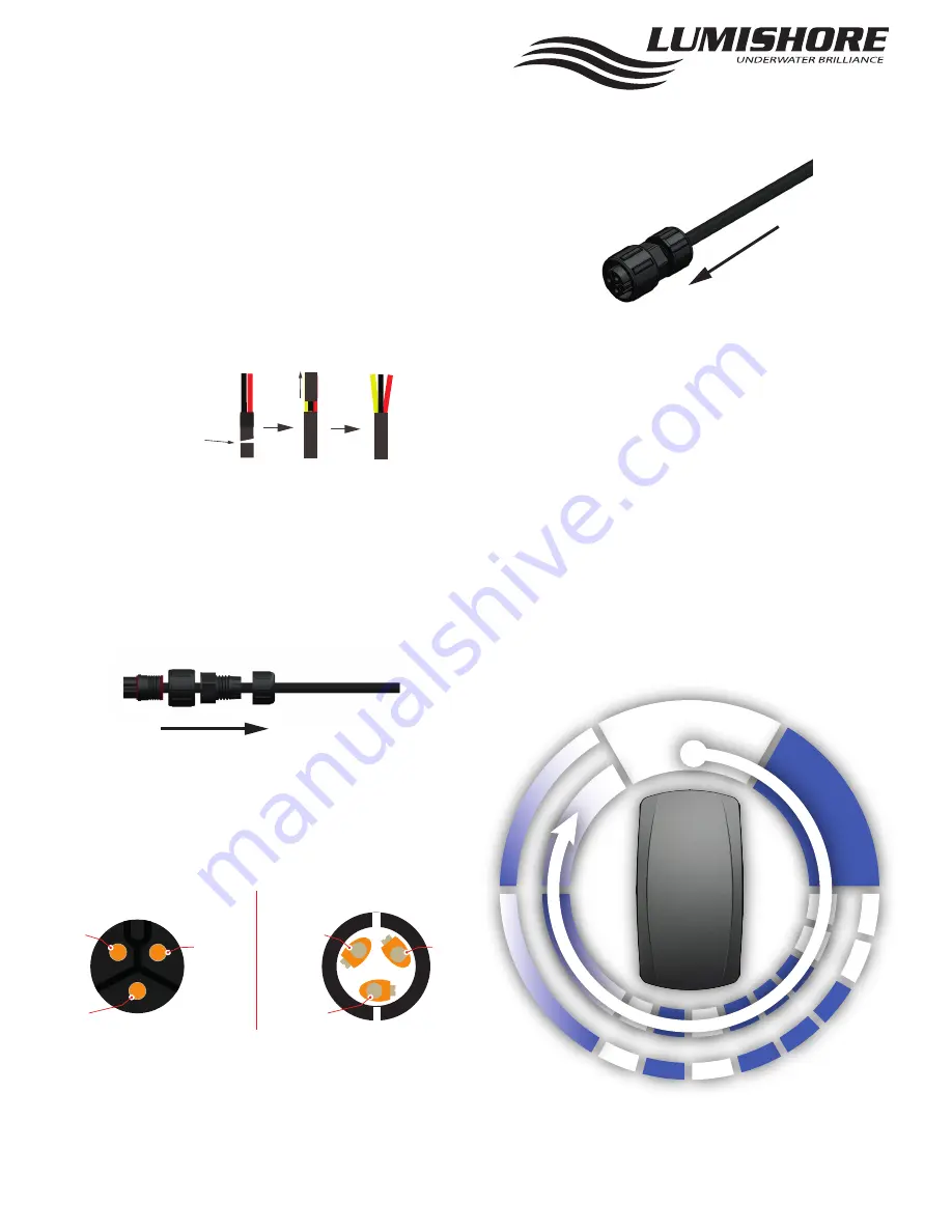
6. Add the field installable connector to the light cables (supplied).
The light cables need to be cut back to reveal the third (data) wire.
Cut the cable just below the
heat shrink. Remove the outer
insulation to reveal the yellow
wire
Trim back the insluation on each core to reveal 4mm of wire.
9. Fit and tighten the strain relief and gland nut onto the connector.
Plug into the hub, taking care to orient the key correctly. Tighten the
cap to make the waterproof seal.
10. Make sure that any unused ports on the hubs have dust caps fitted
(supplied)
11. Connect power to the hub and switch on. Make sure the lights are
tested, and working as expected before the boat goes back in the
water.
The lights operate in White, Blue, White Strobe, Blue Strobe
Synchronised Strobe, Colour Fade mode, and Synchronised Colour
Fade mode.
To change the mode turn the switch OFF / ON (wait a second
before switching back on). The lights will always come on in White
mode when first switched on. To reset the lights to White, switch
off for 5 seconds.
7. Unscrew the back of the connector to reveal the terminals. Fit the
strain relief and gland nut over the cable BEFORE wiring the connec-
tor.
8. Wire the connector as shown below. TAKE CARE to secure the wires
well with the grub screws. Check for any stray strands that could short
to the other pins before fitting the strain relief and gland nut.
Note: Check the wiring is correct before connecting to the hub. Incor-
rect wiring can damage the light.
Field Installable
Connector terminals
viewed from cable side
RED
(12 or 24 V DC)
BLACK
(Ground)
YELLOW
(Data)
BACK VIEW
BLACK
(Ground)
RED
(12 or 24 VDC)
YELLOW
(Data)
FRONT VIEW
SYN
CHR
ONI
SED
ST
RO
BE
WHITE
SY
N
CH
RO
NI
SE
D
FA
DE
RA
ND
OM
FA
D
E
BLU
E
W
H
ITE
ST
RO
BE
B
LU
E ST
ROB
E
ON/OFF
SCENE
LUMISHORE


