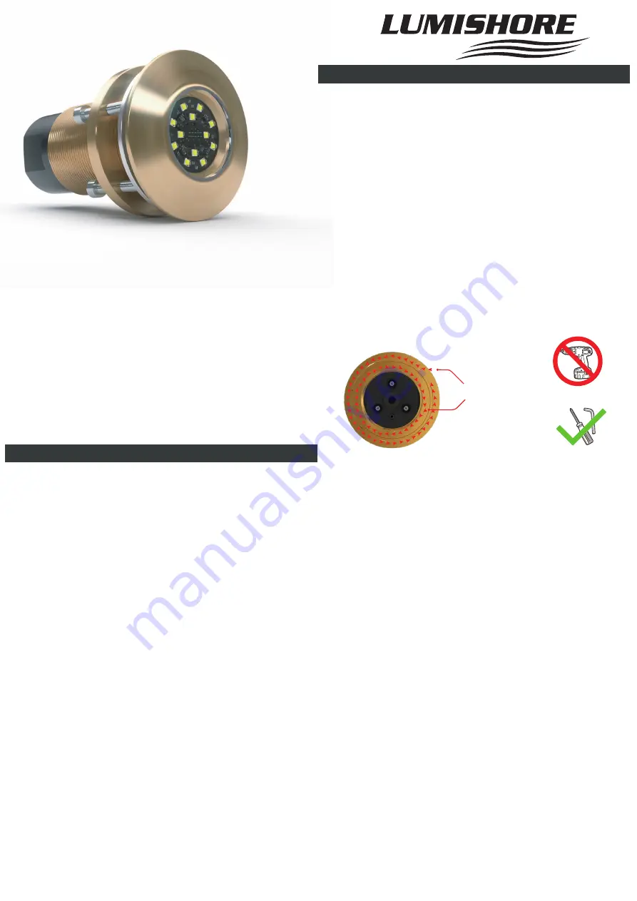
TIX404-ORA-WHITE
Single Color Interchangeable Thru-Hull
10 - 31 VOLT
IP-68
Before you Start
www.Lumishore.com
45-0183 - Rev 1.0
Lumishore UK Unit 2, Technium 1, Kings Road, Swansea, SA1 8PH, UK | +44(0)208 144 1694 | Info@Lumishore.com
1
INSTALLATION AND OPERATION INSTRUCTIONS
Congratulations! You have purchased a LUMISHORE advanced LED
technology underwater lighting system. Every care has been taken to
ensure your compact TIX 404 LED lights arrives in perfect condition,
so please enjoy the ultimate experience in underwater lighting.
Please read the following pages to ensure a complete understanding
of the LUMISHORE LED lighting system before installation.
•
Always ensure that the vessel’s power source and battery are
disconnected or isolated prior to installation
• A qualified professional should carry out both the electrical and
mechanical installation.
• For best underwater illumination, LUMISHORE recommends instal-
lation 4” to 12” (100-300mm) below the minimum load water line.
• Choose a location - The light must be mounted on a flat (not
curved) surface. For underwater installs mount on transom or side
hull only.
• A hole will be drilled to allow the light to be inserted; care must be
taken to ensure there is unrestricted access inside the hull.
• When installing three or more lights, equal spacing 2.5’- 3’ is recom-
mended to give a consistent light pool.
• The light is temperature sensitive and must not be located close to
the exhaust outlet or other heat source.
• Each light should be individually fused 12VDC - 6A, or 24VDC - 4A
fuse.
• For Metal Hull or Carbon Fibre installations an Isolation Kit
(60-0210) will be required.
Mechanical Installation
Tools: Drill, drill bits, marine sealant (Use 3M 4200 (recommended) or
similar), 5mm Allen wrench, rags for clean-up:
Hole Cut Out - 57 mm (2.25“) - With isolation Kit - 64mm (2.5 “)
1. Measure the position of the lights on a flat part of the hull.
Mark carefully, and double-check for internal obstacles.
2. Drill a perpendicular hole through the hull using an appropri-
ate cutter for the hull material. The hole should be the size given
above.
3. The exposed inner hull surface must be properly sealed to
prevent water intrusion into the hull before the Thru-Hull is
secured in place.
4. Before inserting the Thru-Hull light ensure that the hull
surface is free from dirt and grease and remove any existing
anti-foul from the hull surface
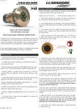
5. Remove the washer and nut from the shaft of the light. Using
an approved adhesive (3M 4200 Marine (recommended) or
similar). Apply a liberal amount of sealant in a continuous bead
around the entire circumference of the sealant groove, and on
the base of the stem and on the shaft of the Thru-Hull.
6. Feed the cable through the hole in the hull avoiding any strain
on the cable. Gently insert the stem of the Thru-Hull light assem-
bly through the hole in the hull.
7. Apply even pressure with a slight circular motion until the
Thru-Hull is flush with the hull surface.
8. From inside the vessel, feed the supplied washer down the
shaft of the Thru-Hull fitting. Screw the locking nut in place
and tighten the retaining bolts so that they are hand tight (less
than 1Nm) -
Do not tighten fully at this stage, excess pressure
will push all of the sealant out.
9. Remove excess sealant that is squeezed from behind the light
with a rag. Use a damp cloth to wipe off excess sealant that has
squeezed out around the light. DO NOT use chemical cleaners or
solvents.
10. Allow the sealant to cure according to the sealant manufac-
turer’s instructions. Once fully cured, using a 5mm Allen wrench,
re-tighten each retaining bolt (force less than
3Nm
).
Care
should be taken not to exceed this force as damage to the
light module or hull of the vessel may occur.
11. Attach the vessel’s bonding protection to the bonding bolt
on the locking ring.
Rear Side
Apply a liberal
amount of sealant
45-0183 Rev 1.0
Single Color Interchangeable
Thru-Hull Underwater Light


