61
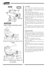
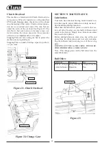
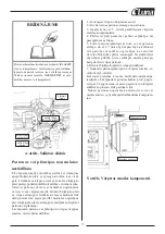
Figure 12. Adjusting graducated dial.
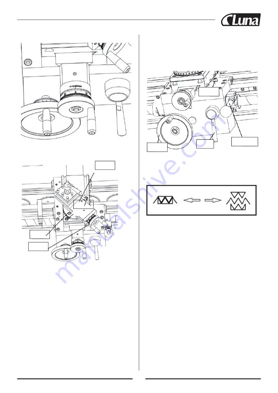
Figure 13. Loosening the compound
slide bolts and compound Cap screws.
4. Loosen the compound Cap screws shown in Figure
13 to allow it to be transversal traveled .
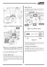
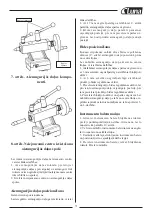
Carriage Hand wheel
The carriage hand wheel (Figure 14)moves the car-
riage left or right along the bed. This manual control
is necessary when setting up the machine for turning
or when manual movement is desired during turning
operations.
Half Nut Lever
The half nut lever can be selected by moving the lever
to the right as in Figure 14 and Figure 15.Use this po-
sition for all feed operations.
Figure 14 .Carriage controls.
left right
Figure 15
When the lever is moved to the left , the lead screw
is selected for threading operations. The lever is only
engaged while cutting threads
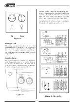
Carriage/Cross Feed Lever
Longitudinal and cross slide powered motions are
controlled by the carriage/cross feed lever. The lever
pivots through pulls and rotates that require moving
the lever up and down (Figure 16).
Compound
slide
Compound
cap screws
Compound
bolts
Compound
handwheel
Half nut
lever
Carriage
handwheel
Carriage/Cross
feed lever
Carriage
lock bolt
Summary of Contents for 21149-0107
Page 1: ...Metal lathe ML1130 21149 0107...
Page 2: ......
Page 5: ...4...
Page 100: ...99 30 pav Past mos prispaud iamosios plok tel s var tai...
Page 132: ...131 Rys 30 ruby regulacyjne listew kli nowych sa wzd u nych...
Page 148: ...147 WIRING DIAGRAM 28 FRAM T BAK T START STOPP...
Page 149: ...148 EXPLOSION DIAGRAM...
Page 150: ...149...
Page 151: ...150...
Page 152: ...151...
Page 153: ...152...
Page 154: ...153...
Page 155: ...154...
Page 156: ...155...
Page 157: ...156...
Page 165: ......
Page 166: ......
Page 167: ......

