62
.
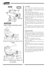
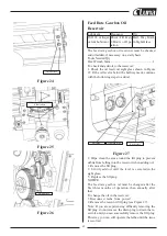
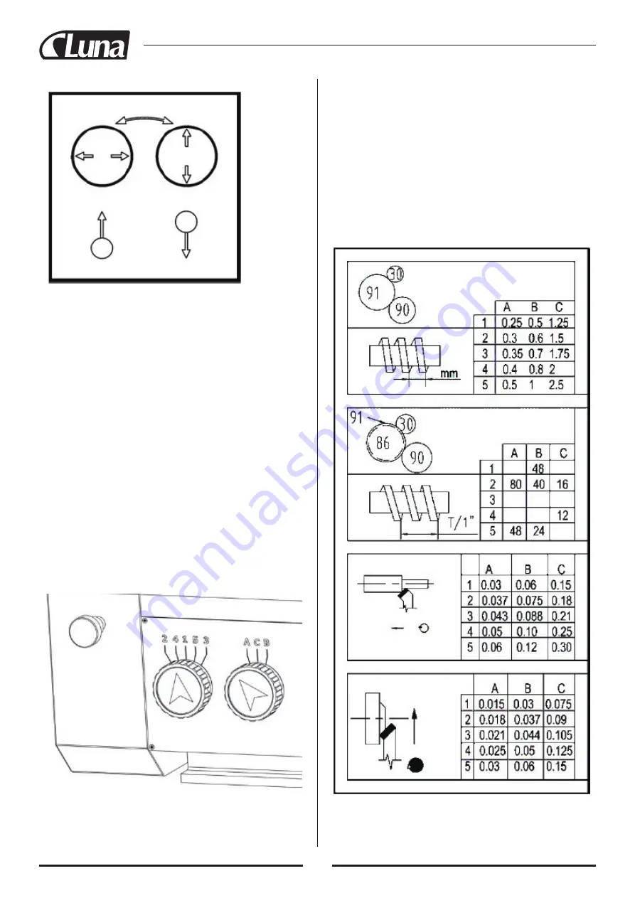
Up Down
Figure 16
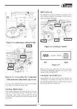
Carriage Lock
The carriage is supplied with a lock bolt on the front
right-hand side of the saddle (see Figure 14). This bolt
locks the carriage in place for increased rigidity when
making face cuts. This lock bolt must be loosened be-
fore attempting to move the carriage manually or with
the power feed.
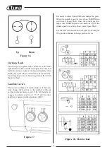
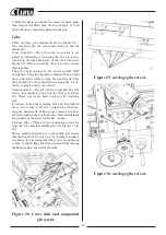
Gearbox Levers
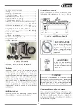
The two levers (Figure 17) at the bottom of the head-
stock change the feed rate, or the number of threads
cut per-inch and metric screw. The left-hand lever
engages in numeric positions 1,2 3,4,5,and the right-
hand lever engages in alpha positions A,B,C.
Figure 17
It is easier to rotate Speed Shaft and change the gears.
When the spindle speed is lower than 660RPM,you
could rotate Speed Shaft; when the spindle speed is
higher than 660RPM,please turn machine off till the
spindle speed turn slowly, then rotate Speed Shaft.
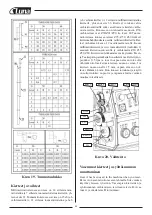
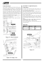
Use the feed rate chart shown in Figure 18 and Figure
19 to position the quick change gearbox levers.
Figure 18. Metric chart
Summary of Contents for 21149-0107
Page 1: ...Metal lathe ML1130 21149 0107...
Page 2: ......
Page 5: ...4...
Page 100: ...99 30 pav Past mos prispaud iamosios plok tel s var tai...
Page 132: ...131 Rys 30 ruby regulacyjne listew kli nowych sa wzd u nych...
Page 148: ...147 WIRING DIAGRAM 28 FRAM T BAK T START STOPP...
Page 149: ...148 EXPLOSION DIAGRAM...
Page 150: ...149...
Page 151: ...150...
Page 152: ...151...
Page 153: ...152...
Page 154: ...153...
Page 155: ...154...
Page 156: ...155...
Page 157: ...156...
Page 165: ......
Page 166: ......
Page 167: ......

