background image


© PROPERTY OF LUNDIX IT SWEDEN, ALL RIGHTS RESERVED – THE DISCLOSURE OR OTHER COMMUNICATION, COPYING, REPRODUCTION AND ANY USE WHATSOEVER IS FORBIDDEN WITHOUT THE WRITTEN AUTHORIZATION 
OF LUNDIX IT. 


SPC SmartBox User Manual 

Revision 

1.1 

Page 

4 of 62 

Reference 

2017-110 

5


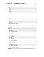
AUTOMATION CONFIGURATION ................................................................................................. 32


5.1


Scenes ......................................................................................................................................................................................... 32


5.1.1


Scene List ......................................................................................................................................................................................................................... 32


5.1.2


Scene Editor .................................................................................................................................................................................................................... 33


5.1.3


Overview .......................................................................................................................................................................................................................... 33


5.1.4


Scene Header .................................................................................................................................................................................................................. 34


5.1.5


Scene Triggers ................................................................................................................................................................................................................ 34


5.1.6


Scene Conditions ........................................................................................................................................................................................................... 35


5.1.7


Scene Actions.................................................................................................................................................................................................................. 36


5.2


Control elements .................................................................................................................................................................... 37


5.2.1


Alarm Areas .................................................................................................................................................................................................................... 37


5.2.2


Alarm Zones .................................................................................................................................................................................................................... 37


5.2.3


Alarm Outputs ................................................................................................................................................................................................................ 38


5.2.4


Actuators .......................................................................................................................................................................................................................... 38


5.2.5


Batteries ........................................................................................................................................................................................................................... 39


5.2.6


Meters ............................................................................................................................................................................................................................... 39


5.2.7


Sensors .............................................................................................................................................................................................................................. 40


5.2.8


KNX Datapoints ............................................................................................................................................................................................................. 40


6


DASHBOARD CONFIGURATION .................................................................................................... 42


6.1


Overview ................................................................................................................................................................................... 42


6.2


Editor main panel .................................................................................................................................................................. 43


6.3


Footer panel ............................................................................................................................................................................. 44


6.4


Object Selector ........................................................................................................................................................................ 44


6.5


Widgets ...................................................................................................................................................................................... 44


6.5.1


Alarm Area Widget ....................................................................................................................................................................................................... 45


6.5.1.1


Configuration Alarm Area Widget ......................................................................................................................... 45


6.5.2


Alarm Zone Widget ...................................................................................................................................................................................................... 45


6.5.2.1


Configuration Alarm Zone Widget......................................................................................................................... 46


6.5.3


Sensor  Binary Widget ................................................................................................................................................................................................ 47


6.5.3.1


Configuration Sensor Binary .................................................................................................................................. 48


6.5.4


Sensor Value Widget.................................................................................................................................................................................................... 48


6.5.4.1


Configuration Sensor Value ................................................................................................................................... 49


6.5.5


Gauge Widget ................................................................................................................................................................................................................. 49


6.5.5.1


Configuration Gauge ............................................................................................................................................. 50


6.5.6


LED Diode Indicator Widget ..................................................................................................................................................................................... 51


6.5.6.1


Configuration LED Diode Indicator ........................................................................................................................ 51


6.5.7


Plot Widget ...................................................................................................................................................................................................................... 52


6.5.7.1


Configuration Plot Widget ..................................................................................................................................... 52


6.5.8


Slider Widget - Interactive ........................................................................................................................................................................................ 53


6.5.8.1


Configuration Slider Widget .................................................................................................................................. 53


6.5.9


Toggle Button Widget - Interactive ....................................................................................................................................................................... 54


6.5.9.1


Configuration Toggle Button Widget .................................................................................................................... 54


6.5.10


Pushbutton Group Widget - Interactive ............................................................................................................................................................... 55


6.5.10.1


Configuration Pushbutton Group  Widget ............................................................................................................ 56


7


APPENDIX ............................................................................................................................................ 57


7.1


SmartBox Hardware Specification ................................................................................................................................. 57


7.2


SmartBox LED Definitions ................................................................................................................................................. 57


7.3


Supported Z-Wave Command Classes .......................................................................................................................... 58


Summary of Contents for SPC SmartBox

Page 1: ...SPC SmartBox User Manual Revision 1 1...

Page 2: ...S FORBIDDEN WITHOUT THE WRITTEN AUTHORIZATION OF LUNDIX IT SPC SmartBox User Manual Revision 1 1 Page 2 of 62 Reference 2017 110 History Record Revision Date Author Comment 1 0 June 2017 Lundix IT Fir...

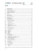
Page 3: ...2 4 1 4 1 SPC FlexC Settings 12 4 1 4 2 SmartBox SPC Communication Settings 13 4 1 5 Sync SmartBox and SPC 14 4 1 6 Conclusion 14 4 2 Z Wave Configuration 15 4 2 1 Configuring Z Wave Network 15 4 2 2...

Page 4: ...43 6 3 Footer panel 44 6 4 Object Selector 44 6 5 Widgets 44 6 5 1 Alarm Area Widget 45 6 5 1 1 Configuration Alarm Area Widget 45 6 5 2 Alarm Zone Widget 45 6 5 2 1 Configuration Alarm Zone Widget 46...

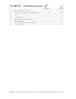
Page 5: ...DIX IT SPC SmartBox User Manual Revision 1 1 Page 5 of 62 Reference 2017 110 7 4 Supported KNX Datapoint Types 58 7 5 Use a network scanning tool to discover IP Address 58 7 5 1 nmap 58 7 5 2 arp 59 7...

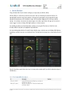
Page 6: ...vices For instance an alarm area mode change or an alarm input status change can be used as a scene trigger to control Z Wave KNX light switches or other actuators An intuitive graphical user interfac...

Page 7: ...SmartBox User Manual Revision 1 1 Page 7 of 62 Reference 2017 110 1 2 Terminology and Abbreviations Term Description FlexC Vanderbilt SPC Flexible Secure Communications Protocol TCP Transmission Cont...

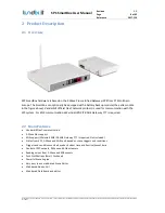
Page 8: ...above Vanderbilt official FlexC network protocol is used for communication with the SPC system For KNX communication a Weinzierl KNX IP BAOS Gateway 777 is required 2 2 Main Features Vanderbilt FlexC...

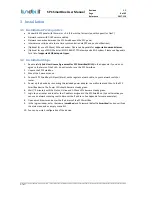
Page 9: ...2 Installation Steps 1 Read carefully End User License Agreement for SPC SmartBox EULA in the Appendix If you do not agree to the terms of the EULA do not install or use the SPC SmartBox 2 Unpack the...

Page 10: ...Default password is Smartbox Network Settings Time and Location SPC Communication Sync SmartBox and SPC 4 1 1 Change SmartBox Password The web GUI username is always smartbox Of security reasons plea...

Page 11: ...and Gateway input fields are disabled IP Address Input text IP address of the device Subnet Mask Input text Subnet mask Gateway Input text IP address of default gateway DNS Server 1 Input text IP addr...

Page 12: ...66 18 Synchronization Interval Option menu Select how often the time should be synced with the NTP servers default every hour Latitude and Longitude Input text Latitude and longitude used for sunrise...

Page 13: ...CT and change following from the default settings SPT Account Code 999 RCT URL or IP Address IP Address of the SPC SmartBox ATP Category Cat 6 Ethernet 6 Open Advanced ATP Settings and change followin...

Page 14: ...SPC panel to SPC SmartBox object database Go to Configuration Object Database select SPC and click on Sync Database with SPC Panel The areas zones and outputs of the SPC panel should then appear in th...

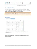
Page 15: ...r battery operated devices Details Button Button to open device detail page Update Route Button Button to request rerouting of the device Request Status Button Button to request status of the device s...

Page 16: ...e instruction in the device manual how to exclude the device Note It can take about 20 seconds before the controller detects the device So please be patient before repeating this step 3 After successf...

Page 17: ...hort description of the device type Description Text A longer description of the device Include Info Text Description how to include the device Exclude Info Text Description how to exclude the device...

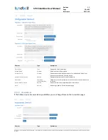
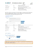
Page 18: ...rent Value Number Shows current value of the parameter Use button Read Value From Device to read this value from the device Read Value from Device Button Request current parameter value from device Ne...

Page 19: ...ions are not defined in the device database you will still be able to configuring the device using a generic interface see below It is very important that you read the Z Wave device manual carefully t...

Page 20: ...ave Network page 4 2 2 6 Advanced Even if the configuration parameters are not defined in the device database you will still be able to configuring the device using a generic interface see below It is...

Page 21: ...ve to configure the link in both the KNX IP gateway and the SPC SmartBox ends 4 3 2 1 Configuration of Weinzierl KNX IP BAOS 777 Gateway SPC SmartBox uses the KNX IP gateway BAOS Webservices to read w...

Page 22: ...ut text KNX IP Gateway password Save Button Saves settings Reset Button Resets form to current settings 4 3 3 Sync SmartBox and KNX System After you have setup the KNX communication you need to import...

Page 23: ...E OR OTHER COMMUNICATION COPYING REPRODUCTION AND ANY USE WHATSOEVER IS FORBIDDEN WITHOUT THE WRITTEN AUTHORIZATION OF LUNDIX IT SPC SmartBox User Manual Revision 1 1 Page 23 of 62 Reference 2017 110...

Page 24: ...hover service in the SPC SmartBox After a 7 day free trail you need to pay a small fee for the App Please see Appendix for help how to create a pushover account and get the keys For email notification...

Page 25: ...How often the notification should be repeated until the notification is acknowledged by the user Only available for Emergency notifications Expire Option Menu Specifies how long time your notification...

Page 26: ...OMMUNICATION COPYING REPRODUCTION AND ANY USE WHATSOEVER IS FORBIDDEN WITHOUT THE WRITTEN AUTHORIZATION OF LUNDIX IT SPC SmartBox User Manual Revision 1 1 Page 26 of 62 Reference 2017 110 Pushover Acc...

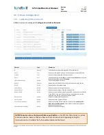
Page 27: ...lement Type Description Id Number Internal object Id Object Text Internal object name Name Text Public object name Type Text Type of object only for SPC KNX and Z Wave Status Number Bitmask with inter...

Page 28: ...g Electric Meter Power Temperature Only Z Wave Unit Text Unit Only Z Wave Value Number Current value updates dynamically Hide in Automation Number 1 the object is hidden in scenes and automation list...

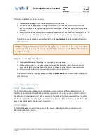
Page 29: ...c the database with the datasource and or recreate the objects in the database For SPC and KNX it is necessary to use the buttons Sync Database with SPC Panel and Sync Database with KNX System to impo...

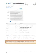
Page 30: ...umber Read only text SmartBox device serial number Firmware Version Read only text Version of installed firmware SmartBox Version Read only text Version of installed SmartBox Application Uptime Read o...

Page 31: ...to backup current system configuration Restore File Browse Button Button to select a backup file on your PC Restore Configuration Button Button to restore a configuration file Normal upgrade procedure...

Page 32: ...er Status Text Status of the scene Enabled Scene is valid and can be started both manually and automatically on trigger Disabled Scene is manually disabled Scene will not start on trigger Invalid Scen...

Page 33: ...nd actions Triggers are used to automatically activate a scene A trigger can be based on time system time sunset sunrise system object value change automation mode global variable or an event from the...

Page 34: ...alf minutes 5 1 4 Scene Header Element Type Description Scene Name Text input Scene name Description Text input Scene description Weekdays Checkboxes Limits the action of the scene to specific days in...

Page 35: ...rm No Alarm Alarm No Tamper Tamper No Trouble Trouble The trigger will have Confirmed Alarm Alarm Tamper and or Trouble status if at least one zone in the area has corresponding status Alarm Zone inpu...

Page 36: ...0 1 KNX DPT2 disable priority and set value to enable priority and set value to 0 1 KNX DPT3 decrease dimming and set step code to increase dimming and set step code to Value Step Code KNX DPT5 DPT9 D...

Page 37: ...es with status Tamper in the area Yes At least one zone in the area has status Tamper Trouble Text No There are no zones with status Trouble in the area Yes At least one zone in the area has status Tr...

Page 38: ...tputs Select Automation Alarm Outputs to list and control the SPC outputs actually the mapping gates Element Type Description Id Number Mapping gate id Name Text Mapping gate name imported from the SP...

Page 39: ...ds Off On Dimmer value 0 99 5 2 5 Batteries Select Automation Batteries to list the battery levels for battery operated Z Wave devices Element Type Description Id Number Z Wave device id and endpoint...

Page 40: ...nce 2017 110 Value Text Current value Updated in real time 5 2 7 Sensors Select Automation Sensors to list the Z Wave sensors Element Type Description Id Number Z Wave device id and endpoint Device Na...

Page 41: ...pdated in real time Control Text Current Control value Updated in real time Command Option menu Select menu Command fields See table below Supported datapoint types and possible commands Datapoint typ...

Page 42: ...to use dashboard tool The dashboard can easy be customized by the end user The dashboard is responsive and can be displayed on any device PC laptop tablet smart phone that has a web browser The dashb...

Page 43: ...load the dashboards from the footer panel see below or from web GUI main menu Dashboard The dashboards are excluded from credentials control so one more way is to load a dashboard directly by giving f...

Page 44: ...current dashboard dashboard in fullscreen mode will be shrinked and history will be lost Go to Smartbox login screen Toogle fullscreen mode Not supported on all platforms 6 4 Object Selector The objec...

Page 45: ...on Label Text Default the label is the area name imported from SPC panel Area 1 in example Area Id Number Area Id 1 in example Area Mode Text Current area mode Unset Partset A Partset B Set Dynamicall...

Page 46: ...OK Inhibit Isolate Soak Tamper Alarm Trouble Circle Circle indicating zone open OR inhibit OR isolated Circle Circle indicating zone closed AND status OK Circle Circle indicating alarm or failure Sho...

Page 47: ...n ON OFF state The state could be 0 1 or a value lower respective higher than a given threshold value Indicator Type Description Description Text Sensor description Light Hall in example Label Text la...

Page 48: ...Button Open object selector see above DESCRIPTION Text Description ICON OFF Option menu Menu to select Off state Icon CIRCLE COLOR OFF Color code Color of circle for Off state RGB LABEL OFF Text Labe...

Page 49: ...et title OBJECT Text read only Datasource variable object OBJECT Button Open object selector see above SIZE Option Menu Size of value characters Small Regular Big Extra Big INCLUDE SPARKLINE Checkbox...

Page 50: ...y Datasource variable object OBJECT Button Open object selector see above UNIT Text Unit Special characters allowed in HTML format e g deg for degree sign MINIMUM Number Gauge minimum value MAXIMUM Nu...

Page 51: ...a given threshold value Indicator Type Description Title Text Widget title LED Indicator ON OFF LED Indicator Colored LED indicator Following colors are supported Grey Yellow Red Green Blue Blinking Y...

Page 52: ...hart widget with a predefined historical time window Note The historical data is not preserved on reload of the dashboard Indicator Type Description Title Text Widget title Plot Area Graph The plot da...

Page 53: ...e extended if necessary 6 5 8 Slider Widget Interactive An interactive slider widget that could be used for control of e g a dimmer actuator Indicator Type Description Title Text Widget title Slider S...

Page 54: ...ontrol of e g a binary actuator Indicator Type Description Title Text Widget title Switch Switch Interactive switch ON OFF text Text Button label ON OFF text 6 5 9 1 Configuration Toggle Button Widget...

Page 55: ...ual Revision 1 1 Page 55 of 62 Reference 2017 110 6 5 10 Pushbutton Group Widget Interactive An interactive pushbutton group widget that could be used for control of e g actuators and scenes Up to 5 b...

Page 56: ...Description TYPE Option Menu Pushbutton group TITLE Text Widget title OBJECT Text read only Datasource variable object OBJECT Button Open object selector Following object types are supported Z Wave Co...

Page 57: ...Solid Orange System is booting up Blinking Orange When the system is set back to default factory setting the Status LED indicator will blink 3 times in orange When the system is restarted the Status L...

Page 58: ...value of a Z Wave enabled electric water or other kind of meters 0x71 COMMAND_CLASS_ALARM The Alarm command class is used to obtain alarm notifications events from devices 0x80 COMMAND_CLASS_BATTERY T...

Page 59: ...the IP address of the SmartBox Just install the app connect to the network and look for manufacturer Connection Technology Systems and you will see the IP address of the SmartBox 7 6 Create Pushover...

Page 60: ...62 Reference 2017 110 5 The next step is to create your own application Click on Create an Application API Token This will open a new form see below Enter a name This can be any name it doesn t need...

Page 61: ...r and it supersedes any prior proposal representation or understanding between the parties If you do not agree to the terms of this EULA do not install or use the PRODUCT The PRODUCT is protected by c...

Page 62: ...ages based in contract tort or otherwise Lundix IT shall have no liability with respect to the content of the PRODUCT or any part thereof including but not limited to errors or omissions contained the...

Reviews: