background image

Tests...Presentation of test menus

6-154

LTO

6.1.2 T

YPICAL


TEST


SCREEN

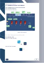
The following screen (lens feeling test) is typical of most tests (see “Operating principle”, page 155):

Micro-switch status

Emergency stop

#1

#5

#3

You are in the lens 

feeler test screen

Exit

Summary of Contents for Briot emotion2

Page 1: ...Instruction Manual FC 00986 Rev00...

Page 2: ...can be modified without prior notice This document has been prepared with great care but some unintentional errors or omissions may occur although every effort has been made to avoid them The manufac...

Page 3: ...recommendation Risk of machine damage or malfunction Follow the instructions carefully Vital preliminary action Before undertaking any action check that the machine is disconnected Electrical hazard...

Page 4: ...designated collection point where electric and electronic equipment may be recycled By ensuring that this product is correctly disposed of you will help prevent potentially harmful environmental and h...

Page 5: ...ob Drilling Positioning of drilling holes Limits of hole positioning Limits related to the thickness of the lens Shape creator function Presentation Procedure Blocking centering system Main blocking s...

Page 6: ...s Procedure Hints Cleaning replacing the removable visor Preliminary remarks Replacing the visor Hints Cleaning the filters and water tank Emptying the water tank Preliminary remarks Procedure Hints H...

Page 7: ...LTO REVISION FOLLOW UP Revision 00 Page New Modified Item...

Page 8: ...1 INSTALLATION...

Page 9: ...other person 2 Cut the two straps on the main packaging carton 3 Pull the main packaging carton upwards and remove it 4 Cut the adhesive tape on the second carton 5 Check that the accessories case and...

Page 10: ...Installation Unpacking the machine 1 9 LTO Illustration 1 1 Unpacking the machine 1 2 4 3 7 Keep the case and the tubes near the machine 6...

Page 11: ...rails follow the procedure below Flow chart 1 2 Removing the shipping rails As shown Illustration 1 2 Removing the fixing screws from the shipping rails 1 With the help of a second person tip the mach...

Page 12: ...D DRILLING REQUIRED ILLUSTRATION The following sketch shows the positioning of the machine on the bench and the openings which must be provided Position your machine correctly before drilling the benc...

Page 13: ...o reach and closed when not in use Water pressure 3 bar maximum Water discharge through a 100 mm diameter pipe The slope must be at least 5 to ensure proper evacuation of the refuse 1 4 1 2 FILTRATION...

Page 14: ...or unscrew the four feet 4 Connect the water drain pipe to the chassis 5 Fit the filter seal between the water supply connection and the valve if you operate in direct water supply 6 Connect the wate...

Page 15: ...Installation Water connections 1 14 LTO As shown 1 2 Pump power connector Level 3 4 6 7 Settling tank DIRECT WATER SUPPLY 5 CLOSED CIRCUIT 4 6 Filtration tank...

Page 16: ...Flow chart 1 4 Shipping safeties As shown Illustration 1 6 Shipping safeties IMPORTANT KEEP THE SAFETY ACCESSORIES AND SHIMS WITH THE PACKING BOXES IN CASE OF FUTURE TRANSPORT OF THE MACHINE 1 Remove...

Page 17: ...ent to the edger proceed as follows Flow chart 1 5 Electrical connections As shown Illustration 1 7 Electrical connections Note The pump and reader illustrations are not the property of the manufactur...

Page 18: ...switched off On Off switch OFF and mains plug disconnected 2 Fit the lens clamping and lens holder adaptors on the shafts 3 Plug in the machine and switch on On Off switch lit 4 Start a dummy cycle a...

Page 19: ...2 PRECAUTIONS FOR USE...

Page 20: ...electrical storm or when the machine is left unattended for a long period Keep the machine away from any source of heat A radiator is a heat source which can be detrimental to the correct operation of...

Page 21: ...to the di splay see paragraph Adjusting the touch screen chapter Settings adjustments Clean the touch screen with a soft clean dry cloth Scanform zone To ensure an optimum working life of the equipmen...

Page 22: ...perfectly water tight Change the water in the tank regularly if your machine operates in closed water circuit mode Make regular checks of the condition of the feeler tips and change them if they are w...

Page 23: ...3 USING YOUR EDGER...

Page 24: ...rts Illustration 3 1 Overall view of the edger On the Perception2 machine the Scanform is replaced by a map pockets MAIN PARTS The exploded view below Illustration 3 2 shows the main parts of the edge...

Page 25: ...and shape Enter the data for one eye or both Enter the shape of a pattern or a demonstration lens automatic detection of either of them 3 1 2 4 SHAPE CREATOR FUNCTION The Shape Creator function enable...

Page 26: ...eparation production steps of the spectacles 1 Creation Scanform Selection of a job OMA loading 2 Centering blocking system 3 Edging operation The parameters for each operation are defined in each of...

Page 27: ...The buttons or menus which can be enabled are highlighted those which cannot be enabled are grayed Example Can be enabled Cannot be enabled SEVERAL POSSIBLE SELECTIONS You can enable one or more func...

Page 28: ...entered and if a job exists with this number in the Job database it is displayed and can then be used or copied over with a new shape entry Note Loading a job causes the lens material data finishing d...

Page 29: ...atabaser Screen 3 3 Pattern base screen The calculator is displayed to enter a job No to be loa ded from the OMA When the calcula tor is displayed a bar code can be entered Short press The job is sent...

Page 30: ...ulator is opened in order to enter a Job number if this Job already exists in the Jobs database this Job is displayed Loading a Job number from the OMA server configurable function Sending the Job to...

Page 31: ...nt data base 1 2 3 Previous page Move up Move down Next page Confirm Return to creation screen 1 Pressing on the Job selection key is used to access the com pete list of saved jobs 2 Go to the desired...

Page 32: ...d push the centering nose and the lower parts should be positio ned between the Scanform clips Scanform Select the side s to be entered Select the entry type Automatic insertion Semi automatic inserti...

Page 33: ...efer to the unpacking guide supplied with your machine Illustration 3 3 Tracing a lens It is possible to configure the side s automatic detection To do this make the longer line on the nose side The l...

Page 34: ...upport For greater precision of measurement the external face of the presentation lens must be in contact with the bearing surface Illustration 3 5 Positioning the lens Press the Gravitech button to l...

Page 35: ...n 3 2 3 2 2 SIDE OF THE PRESENTATION LENS OR PATTERN Position the tip icon on the correct side according to the presentation lens or pattern left or right For this purpose press the icon to switch to...

Page 36: ...reatment screen Screen 3 9 Parameter definition screen drilling plan Measurement with detection of drilling holes Measurement wi thout drilling holes Eliminating the holes Visualize theaxis treatment...

Page 37: ...creen 3 2 3 2 5 VISUALIZATION OF THE AXIS TREATEMENT You may conduct a visualization of the axis treatment image if it exists In this way you can have access to the manual adjustment of the axis For t...

Page 38: ...efined in the machine settings You may change the proportional compensation value using the entry button 2 If no compensation is necessary simply press the button 1 Screen 3 12 Lens compensation scree...

Page 39: ...ct the frame type The frame type shall enable the corresponding oversize dimensions to be applied to the edging Plastic frame For this frame the edging oversize will be the addition of the plastic fra...

Page 40: ...is possible to correct this error by applying a Mirror function on the shape Screen 3 14 Example of screen before application of the mirror function Screen 3 15 Example of screen after application of...

Page 41: ...Press the Digiform tab 3 2 4 1 PRESENTATION The Digiform function is used to change any initial job into a new job To modify the shape of a pattern use the functions on the bottom of the screen Scree...

Page 42: ...reen area to stretch the lower part of the shape 2 The new shape can then be viewed in red You can confirm 3 Screen 3 17 Example of deformation Screen 3 18 Example of lower part deformation entry scre...

Page 43: ...s follows to pivot a shape Screen 3 19 Pivoting a shape 1 Open the initial saved shape 2 Press the rotation key Using the number key pad enter the desired degree Example 10 4 Use the new shape as if i...

Page 44: ...lect the coordinate to be modified X Y Dia using the navigation keys Enter the desired value by increment decrement and Check the coordinates of the selected hole as well as its diameter Navigation ar...

Page 45: ...rilled at a 10 angle from the front face The smallest hole diameter that can be drilled with the mill bit is 1 mm Note When the job is received on the edger if it includes at least one hole whose diam...

Page 46: ...n black in the screen Some holes displayed in blue in the screen may be impossible to drill after they have been felt holes too deep unadapted angle unadapted end piece etc The ring formed by the edge...

Page 47: ...le it is possible that the maximum drilling length in the drilling direction may be exceeded This results in a non through hole Caution Non through hole for lens thickness 8 mm The quality of the fina...

Page 48: ...s the key Screen 3 21 Access screen to the SHAPE CREATOR function 3 2 6 2 PROCEDURE 3 2 6 2 1 BLOCKING THE AXIS SETTING CROSS You are sent to the screen allowing you to enter the shape of your frame p...

Page 49: ...oint entry screen To insert and position a point press button 1 you may then define the position of the latter using browsing arrows 2 It is possible to select your frame 3 and to apply an oversize de...

Page 50: ...Using your Edger Usual procedure 3 49 LTO Then you will be sent to the frame display screen At any time you may return to the Shape Creator screen by clicking on Screen 3 25 Frame shape display screen...

Page 51: ...n L or R shows which side will be blocked 2 Place a lens holder corresponding to the lens to be blocked NOTE To block a lens which has to be regrooved or a small lens 45 mm it is preferable to use the...

Page 52: ...st be on the horizon tal line Centering a bifocal lens The top of the segment must be tangential to the blue line The sides of the segment must be tangential to a pair of vertical lines of the same co...

Page 53: ...Using your Edger Usual procedure 3 52 LTO Block support 5 6 Blocker head Blocker arm 7 9 8...

Page 54: ...INDEX COLOUR The index and colour have no effect on the centering function TREATMENT The lens treatment in particular the anti reflective coating has no effect on the centering function HEIGHT Lay th...

Page 55: ...ENTATION Enter the Edging tab Screen 3 26 Edging tab general icons Oversize to boxing width Select lens Lens materials Finishing Sub finishing Launch the ed ging process Rear safety bevel Front safety...

Page 56: ...chart 3 1 Edging cycle sequence Note The selection of the Manual finishing type beveling grooving leads to a modification of the normal sequence of the edging cycle emotion2 perception2 Closing of th...

Page 57: ...emorised and preselected for the following lens Check the parameter values Create a Job in the creation interface Select the lens material Select the type of lens Select the finishing type Select the...

Page 58: ...ing chamber When the edging cycle is stopped or interrupted open the visor press this button Result the lens clamp shaft opens automatically remove the edged lens without removing the block so as to b...

Page 59: ...Lens Type Icons Hydrophobic Specific cycle suitable for lenses with hydrophobic treatment Fragile Specific cycle suitable for lenses that you consider to be fragile the roughing phase is slower than...

Page 60: ...Limits of production of a bevel 3 2 8 4 3 INCLINED GROOVE FINISHING Illustration 3 8 Limits of production of an inclined groove Rimless Grooving Bevel Front face Rimless Min height of finished lens 1...

Page 61: ...33 of the lens thickness from the front face Groove 50 Bevel The apex of the bevel is positioned at 33 of the lens thickness from the front face Groove Front Face Bevel The bevel follows the front fac...

Page 62: ...d as follows Flow chart 3 3 Production of a job with rimless finishing Screen 3 31 Example of the production of a job with rimless finishing Create a Job in the creation interface Select POYCARBONATE...

Page 63: ...a job with Drilling finishing Screen 3 32 Example of the production of a job with Groove finishing Create a Job in the creation interface Select HI plastic lens material Select NORMAL lens type Select...

Page 64: ...bevel positioning we advise you to choose Manual type from the main screen During the cycle when the manual finishing screen is displayed press the Manual Bevel button select the type of bevel you wis...

Page 65: ...Using your Edger Usual procedure 3 64 LTO Screen 3 33 Example of the production of a job with rimless finishing Without polishing Without oversize Mineral lens Bevel finishing 50 Bevel Fragile type...

Page 66: ...ront face of the lens is greater than 0 4 mm and the distance between the rear edge of the groove and the rear face of the lens is greater than 0 4 mm depth of safety bevel 0 2 mm If you make a retouc...

Page 67: ...Using your Edger Usual procedure 3 66 LTO 3 2 9 POLISHING Note The presence and order of the icons displayed on the screen depend on the job data Screen 3 35 Polishing Icons With Without...

Page 68: ...ws Enter the correction value Check the entered value Start the lens blocking operation 3 3 1 2 3 RESULT The lens is edged and the initial dimension has been increased or decreased by the entered valu...

Page 69: ...job the following characteristics cannot be modified from one lens to another Lens material Finishing type Polishing type You may only modify the following characteristics Lens type Sub finishing type...

Page 70: ...ishing and modify its position if desired IMPORTANT NOTE The indices of zones A and B indicate the same finishing angular position When you move one the other moves as well 3 3 3 2 PRESENTATION 3 3 3...

Page 71: ...ens section at posi tion of index Lens thickness A B Developed lens profile Lens shape seen from the front Re feeling Displacement of the groove forward Displacement of the groove darkward Modificatio...

Page 72: ...been redirected automatically to the manual finishing screen for the following reasons The bevel or the groove are outside the lens The bevel is too far back Irregular points were detected during feel...

Page 73: ...n the whole finishing move it in one direction to the required position Then do the same from the opposite point 3 3 3 4 3 SPECIAL CASES After the lens feeling you may have been redirected automatical...

Page 74: ...tion to the required position Then do the same from the opposite point To make a safety bevel of any type the minimum distance between the bevel apex and the front rear face must be greater than 1 6 m...

Page 75: ...ult the apex of the bevel is positioned at 1 3 of the lens thickness from the front face Move the bevel apex and position it as you wish To the rear To the front To the front To the rear Check that fi...

Page 76: ...atically to guarantee the lens resistance To make a groove of any type the minimum distance between the front face of the lens and the front edge of the groove or the rear face and rear edge must be g...

Page 77: ...he front face Move the finishing and position it as you wish To the rear to the front Scan the lens profile as you wish To the front To the rear Check that finishing Position the middle of the groove...

Page 78: ...times successively The lens is felt 0 5 mm closer to the interior each time If the three successive feeling operations are not enough the lens is too small and cannot be edged Confirm the message Comp...

Page 79: ...oughing 10000 lenses Plastic roughing 50000 lenses Finishing 8000 lenses 10000 lenses Polishing 6000 lenses Safety bevel 5 000 lenses per wheel side Grooving 5000 lens Beveling Minimum lens thickness...

Page 80: ...2 mm at Boxing width Minimum distance between the apex of the bevel and the front rear face to produce a safety bevel 1 6 mm Min distance between the front face of the lens and the front edge of the g...

Page 81: ...4 CONFIGURATION...

Page 82: ...the top right of the current screen If you are working with the Personalisation screen the edger will be dis played on the top right of the screen 4 1 1 2 ACCESS EXIT 4 1 1 2 1 TO ACCESS THE SCREEN To...

Page 83: ...RIPTION The personalisation menu access screen is shown below Screen 4 2 Personalisation menu access screen 4 1 2 2 ACCESS EXIT 4 1 2 2 1 TO ACCESS THE SCREEN 4 1 2 2 2 TO EXIT THE SCREEN Adjustment o...

Page 84: ...first target your needs with precision and then modify the values with full knowledge of our recommendations 4 2 2 PROCEDURE To adjust the setting values proceed as follows Flow chart 4 1 Adjustment o...

Page 85: ...ect value If you wish to exit the number key pad use the ESC key The previous default value will then be applied again TABLE 1 Sub finishing type Default value Lower limit Upper limit Incrementation 0...

Page 86: ...e standard setting values can affect the performance of the machine If you wish nonetheless to use the value adjustment function first target your needs with precision and then modify the values with...

Page 87: ...tion for plastic and metal frames To enter a correction for plastic frames To enter a correction for CR39 lenses To enter a correction for High Index lenses Adjustment of setting values NOT TAKEN INTO...

Page 88: ...EEN 4 4 1 3 2 TO EXIT THE SCREEN To save the settings You are in the General Operation screen of the machine Dialog language Press again until the language of your choice is displayed Compensation of...

Page 89: ...SIZE COMPENSATION ACCORDING TO WHEEL CONDITION 4 4 2 3 1 PRINCIPLE A wheel becomes very abrasive after dressing This can lead to some instability in the dimensions of edged lenses following wheel dre...

Page 90: ...o account and you return to the personalisation menu access screen Don t confirm the message The configuration is not taken into account and you return to the personalisation menu access screen The pr...

Page 91: ...ing the communication parameters 4 5 1 3 ACCESS EXIT 4 5 1 3 1 TO ACCESS THE SCREEN 4 5 1 3 2 TO EXIT THE SCREEN 4 5 1 4 ENABLING DISABLING COMMUNICATION FUNCTIONS 4 5 1 4 1 PRINCIPLE According to the...

Page 92: ...5 MAINTENANCE...

Page 93: ...e current screen If you are working with the Maintenance screen the hand holding the spanner will be displayed on the top right of the screen 5 1 1 2 ACCESS EXIT 5 1 1 2 1 TO ACCESS THE SCREEN To reac...

Page 94: ...below Screen 5 2 Maintenance menu access screen 5 1 2 2 ACCESS EXIT 5 1 2 2 1 TO ACCESS THE SCREEN 5 1 2 2 2 TO EXIT THE SCREEN Changing the lens feeler tip Dressing the wheels Emptying the settling t...

Page 95: ...NTS The illustrations below will help you to identify the parts of the edger on which you will be working during main tenance operations Lens feeler tip Replacement Settings Visor Cleaning and replace...

Page 96: ...ter Replace the flexible lens clamp adaptor pad regularly every 1000 lenses Replace the mill bit when a message asks you to do so 1 hour of total drilling time Check the condition of the lens feeler t...

Page 97: ...Do not use products such as water or chemical agents Ethyl alcohol can be used when a dry cloth is not efficient enough to remove stubborn stains The GUARANTEE WILL NOT APPLY to damage caused by impr...

Page 98: ...sing a compressed air spray 1 Switch OFF the machine if it is ON 2 Manually open the Scanform and lift up the stylus head Hold the elements in this position without applying force 3 Place a sheet of p...

Page 99: ...tube you want to replace example Figure 1 in order to remove it NOTE Only the upper frame clip tubes can be replaced 4 Fit the new frame clip tube make sure the tube is engaged fully home in its shaf...

Page 100: ...r movement from the centre outwards 5 6 2 CLEANING THE LOWER LENS OF THE COLLIMATOR To replace the lower lens of the collimator proceed as follows NOTE It is recommended to clean the lower lens of the...

Page 101: ...BE DANGE ROUS BOTH FOR THE USER AND THE MACHINE 1 Switch OFF the machine if it is ON 2 Disconnect the power cord from the wall socket 3 Remove the rear cover 4 Remove the fuse from the fuse holder on...

Page 102: ...rotected when handling the lens holder adaptor and feeler tip 5 7 1 2 PROCEDURE To replace the flexible lens clamp adaptor pad follow the procedure below Flow chart 5 1 Replacing the lens clamp adapto...

Page 103: ...6 Fit an 8 mm spanner on the chuck nut 7 Loosen the nut with one turn of the spanner to free the bit 8 Use pliers to remove the bit from the chuck 9 Fit a new bit in the chuck We advise you to apply a...

Page 104: ...om the chuck because of possible scale deposits In this case apply a small quantity of a common scale remover leave it for a few moments and then remove the bit Use bits supplied by your Briot represe...

Page 105: ...ler tips 1 2 3 4 5 Hold the holder and immobilise the feeler arm 6 Insert a screwdriver or an Allen wrench in the hole of the removable feeler tip 7 Tilt the right feeler tip carefully to unscrew it 8...

Page 106: ...because that could alter the quality of the work produced by the machine If you observe any malfunctioning after changing the feeler tips contact your Briot representative FRAGILE MOUNTING Removable l...

Page 107: ...below to dress a wheel Flow chart 5 4 Dressing a wheel 5 7 4 3 HINTS Dress the wheels when a message asks you to do so 1 2 3 4 OR OR According to your selection 5 Make sure large adaptors are fitted 6...

Page 108: ...intenance Regular maintenance of the edger 5 107 LTO Illustration 5 6 Dressing a wheel 5 4 6 Ensure that the dres sing disc is correctly centered using the in dentations intended to receive the adapto...

Page 109: ...d above Only Step 5 changes 5 7 5 3 HINTS Regular cleaning of the visor increases the visibility of the interior of the edging chamber and the operations under way Operating in closed circuit mode aff...

Page 110: ...Maintenance Regular maintenance of the edger 5 109 LTO Illustration 5 7 Cleaning and replacing the removable visor Screw Outer visor Inner visor 1 2 3 4 or 5...

Page 111: ...pipe with a 20x27 connection 5 7 7 2 PROCEDURE To empty the settling tank follow the procedure below Flow chart 5 5 Emptying the settling tank 1 Fit a discharge pipe on the same side as the valve and...

Page 112: ...cess Always check the water tightness of the unit before restarting the machine Check the connections of the drain water supply and pump pipes Ensure that the discharge valve is closed Check that all...

Page 113: ...HOW To remove the machine covers follow the procedure below Flow chart 5 6 Removing the covers As shown Illustration 5 10 Removing the covers 5 8 2 REPLACING THE COVERS To replace the machine covers...

Page 114: ...or pad 17 across flats 11 38 171 Every 1000 lenses Removable lens feeler tip S180191 Every 3000 lenses Lens holder adaptor Large Size 11 90 375 If necessary Lens holder adaptor Small Size 11 90 406 If...

Page 115: ...creen is shown below Screen 5 3 Setting menu access screen 5 10 1 2 ACCESS EXIT 5 10 1 2 1 TO ACCESS THE SCREEN 5 10 1 2 2 TO EXIT THE SCREEN Touch screen adjustment You are in the User Set tings menu...

Page 116: ...re the same go to the next step If the values are not the same enter the values marked on the tool using the keys and Note the value R must be close to 40 mm the value H must be close to 24 mm 6 Posit...

Page 117: ...he measured values which are displayed on the screen Adjustment is correct when all the dots in front of the parameters are green Note If one or more dots are red repeat the step by pressing the key I...

Page 118: ...djustment and proceeds to the next one 25 When the icon is displayed insert the rectangular pattern No 14 04 191 on the pattern holder 26 Position the tool in the frame holder Figure 4 Figure 4 27 Pre...

Page 119: ...chine then switches automatically to this screen 5 10 3 2 PROCEDURE Follow the steps below to adjust the feeling Flow chart 5 7 Feeling adjustment Enter the thickness value of the tool 1 2 3 4 Leave t...

Page 120: ...ctly fitted on the shaft You must neither force the fitting nor feel any play The feeling setting can be incorrect if the tool is badly positioned This factor also affects the quality of the work prod...

Page 121: ...hen you measure the lens size with a digital caliper keep the lens in the same plane as the caliper Take two consecutive measurements 90 apart and record the average value with the number keypad Perfo...

Page 122: ...e size of the lens with a caliper 17 18 Enter the value using the number key pad 19 20 Check the position of the apex of the bevel with a linen counter The apex must be in the centre of the edge of th...

Page 123: ...of the edge of the lens 29 If the apex of the bevel is off centered enter the value of the shift using the number key pad Apex too close to the rear face enter a negative value Apex too close to the f...

Page 124: ...e You can use marked lenses P N 1404274 or flat plastic lenses P N 1000205 marked with a line in the middle to indicate the shaft BEFORE STARTING A CALIBRATION MAKE SURE THAT THE BLOCKING SYSTEM SHAFT...

Page 125: ...ns holder adaptors on the shafts Place the lens in the edging chamber and tighten it 7 8 After edging remove the lens without unblocking it and wipe it off Place the lens in superposition with its sha...

Page 126: ...Maintenance Adjustments 5 125 LTO Screen 5 5 Post edging shaft adjustment screen Screen 5 6 Shaft adjustment screen left eye check...

Page 127: ...e side of the lens and record the result Turn the lens 90 and start again The lens diameter corresponds to the average of the two measured values Note Calibration must be performed when the edging tim...

Page 128: ...ing size Flow chart 5 9 Adjustment of the mineral roughing size 1 2 3 4 Centre and block a glass lens 5 Fit the lens clamping and lens holder adaptors on the shafts Place the lens in the edging chambe...

Page 129: ...not be modified from these screens 5 10 7 2 ACCESS EXIT NAVIGATION 5 10 7 2 1 TO ACCESS THE SCREENS 5 10 7 2 2 TO EXIT THE SCREENS 5 10 7 2 3 TO NAVIGATE FROM ONE SCREEN TO ANOTHER To access the next...

Page 130: ...en 5 10 8 2 PROCEDURE Follow the steps below to adjust the touch screen Flow chart 5 10 Adjustment of the touch screen 5 10 8 3 HINTS Make sure to press exactly on the crosses during adjustment Otherw...

Page 131: ...Maintenance Adjustments 5 130 LTO Screen 5 8 Adjustment of the touch screen...

Page 132: ...ss screen Since the last wheel dressing Note The Statistics menu type is shown by the icon which is displayed on the top right of the current screen 5 11 1 2 ACCESS EXIT 5 11 1 2 1 TO ACCESS THE SCREE...

Page 133: ...5 11 2 1 1 CONTENT The incident log may be consulted according to four themes Consultation of the general list of incidents which have occurred incidents warnings and information Consultation of the...

Page 134: ...ist menu Incident 15 is the most recent It occurred on lens 138 and is of type M0 I66 Scroll down and con sult the incidents from the oldest to the most recent Go to the screen showing the incidents l...

Page 135: ...lens material Statistics based on bevel and rimless finishing Statistics based on polishing Statistics based on safety bevel Statistics based on groove finishing Statistics based on retouch Statistics...

Page 136: ...general statistics is shown below Screen 5 11 Consulting the edger general statistics screen Number of machine starts Scanform You are in the Machine Statistics menu Digiform Centering Blocking syste...

Page 137: ...n the last wheel dressing The display screen for statistics based on the last wheel dressing is shown below Screen 5 12 Dressing maintenance screen Screen 5 13 Consulting statistics based on the last...

Page 138: ...s based on polishing is shown below Screen 5 15 Consulting statistics based on polishing Example As shown in the above screen 2 lenses with bevel finishing and polishing have been edged since the mach...

Page 139: ...on safety bevel is shown below Screen 5 16 Consulting statistics based on safety bevels 5 11 2 2 3 7 Display screen for statistics based on groove finishing The display screen for statistics based on...

Page 140: ...ting statistics based on retouch 5 11 2 2 3 9 Display screen for statistics based on user maintenance The display screen for statistics based on user maintenance is shown below Screen 5 19 Consulting...

Page 141: ...atistics 5 140 LTO 5 11 2 2 3 10 Display screen for statistics based on Digiform Screen 5 20 Consulting statistics based on Digiform 5 11 2 2 3 11 Display screen for drilling statistics Screen 5 21 Co...

Page 142: ...41 LTO 5 11 2 2 3 12 Display screen for Scanform statistics Screen 5 22 Consulting Scanform statistics 5 11 2 2 3 13 Display screen for Rimless Dressing statistics Screen 5 23 Consulting Rimless Dress...

Page 143: ...42 LTO 5 11 2 2 3 14 Display screen for the centering blocking system statistics Screen 5 24 Consulting the centering blocking system statistics 5 11 2 2 3 15 Display screen for settings statistics Sc...

Page 144: ...other job 0x5 Unknown job number The job number you are trying to load does not exist on the ser ver Check the job number and load another number 0x7 Do you want to re edge the same lens You have just...

Page 145: ...lycarbonate lens material In the personalisation menus you have excluded this parame ter Therefore the edger cannot ac cept this job Confirm the message If you wish to load this job no netheless chang...

Page 146: ...shing In the personalisation menus you have excluded this parame ter Therefore the edger cannot ac cept this job Confirm the message If you wish to load this job no netheless change the personali sati...

Page 147: ...ent groove sub fi nishing In the personalisation menus you have excluded this parame ter Therefore the edger cannot ac cept this job Confirm the message If you wish to load this job no netheless chang...

Page 148: ...fety bevels In the personalisation menus you have excluded this parame ter Therefore the edger cannot ac cept this job Confirm the message If you wish to load this job no netheless change the personal...

Page 149: ...esponse from server within time limit You have tried to load a job but the edger has not received a si gnal from the server Check that The server is switched on The OMA cord is correctly con nected to...

Page 150: ...or a groove NO the lens is not edged Re move the lens from the edging station 0x40B Internal safety bevel gro ove will not be made Do you want to continue Internal safety bevel and groo ve cannot be...

Page 151: ...n 1 mm has been detected in at least one point of the lens YES The lens is edged with rim less finishing NO The cycle is stopped Remo ve the lens from the edging station 0x41B Lens too small Feeling c...

Page 152: ...the risk of using a fouled wheel The risk of lens size error is increased and so is the edging time The message is displayed at each machine startup 0x902 Dressing impossible Wrong disc thickness The...

Page 153: ...6 TESTS...

Page 154: ...access screen is shown below Screen 6 1 Test access screen Note CBRP Safety Bevel Grooving Drilling system 6 1 1 2 ACCESS EXIT 6 1 1 2 1 TO ACCESS THE SCREEN 6 1 1 2 2 TO EXIT THE SCREEN Exit Tempera...

Page 155: ...t menus 6 154 LTO 6 1 2 TYPICAL TEST SCREEN The following screen lens feeling test is typical of most tests see Operating principle page 155 Micro switch status Emergency stop 1 5 3 You are in the len...

Page 156: ...ng principle is as follows Flow chart 6 1 Operating principle of a typical test screen 6 2 1 3 TEST SEQUENCE Tests must be undertaken in a logical sequence The tests which appear grayed cannot be carr...

Page 157: ...e test press the switch of the element you wish to test Observe the test To stop the test press the switch again 6 2 2 1 2 SCREEN WITH MICRO SWITCHES AND PHOTOCELLS Manually operate the micro switch o...

Page 158: ...7 TECHNICAL SPECIFICATIONS...

Page 159: ...grooving in single width i e W 0 6 mm Nylon thread or double width i e W 1 2 mm Drilling wide choice of holes Through holes Notches Elongated holes Drilling at fixed 10 angle Safety beveling of front...

Page 160: ...on Category II Operating temperature 13 C 35 C Relative humidity 10 80 Maximum water pressure 3 Bars Maximum water pressure on pump 3 Bars Controlled power output for the pump 230 V 50 Hz 120 V 60 HZ...

Page 161: ...2002 95 EC Di 2002 96 EC MEETS THE FOLLOWING CEM DIRECTIVES Di 2004 108 EC EN 55022 Class B EN 61000 3 2 EN 61000 3 3 EN 61000 6 2 UL STANDARDS FOR 115 V VERSIONS UL CSA 61010 1 THE MANUFACTURER CANNO...

Page 162: ...2 rue Roger Bonnet 27340 PONT DE LxARCHE FRANCE T l 33 50 232 989 132 Fax 33 50 235 020 294...

Reviews: